Method for driving droplet ejecting head and droplet ejecting device

a technology of droplet ejection and droplet, which is applied in the direction of printing, other printing apparatus, etc., can solve the problems of difficult application of liquid pressure and inability to increase printing speed, and achieve the effect of suppressing residual vibration, and enhancing the driving frequency of the droplet ejection head

Inactive Publication Date: 2010-05-06
SEIKO EPSON CORP
View PDF0 Cites 4 Cited by
  • Summary
  • Abstract
  • Description
  • Claims
  • Application Information

AI Technical Summary

Benefits of technology

[0011]An advantage of the invention is to provide a method for driving a droplet ejecting head that is more suitable for suppressing a residual vibration than a related art method, and a droplet ejecting device for driving the droplet ejecting head using the method.
[0012]According to a method for driving a droplet ejecting head of a first aspect of the invention, the droplet ejecting head includes a liquid pressure chamber communicating with a nozzle hole, and a pressure application unit applying pressure on liquid stored in the liquid pressure chamber for ejecting a droplet from the nozzle hole. The method includes applying on the liquid stored in the liquid pressure chamber pressure having a waveform whose phase is delayed by 90 degrees from a waveform of a residual vibration of the liquid by the pressure application unit after an ejection of the droplet from the nozzle hole. Therefore, the residual vibration after the ejection of the droplet can be quickly suppressed, and the return movement after the ejection of the droplet can be promptly performed. Accordingly, a driving frequency of the droplet ejecting head can be enhanced.
[0013]According to a method for driving a droplet ejecting head of a second aspect of the invention, the droplet ejecting head includes a liquid pressure chamber communicating with a nozzle hole, a vibration plate formed in the liquid pressure chamber, and a fixed electrode disposed so as to face the vibration plate with a predetermined interval between the fixed electrode and the vibration plate, and applies pressure to liquid stored in the liquid pressure chamber by deforming the vibration plate by an electrostatic force generated by a driving voltage applied between the vibration plate and the fixed electrode for ejecting a droplet from the nozzle hole. The method includes applying between the vibration plate and the fixed electrode a vibration control voltage having one of a rectangular waveform and a trapezoidal waveform for controlling a residual vibration of the liquid after an ejection of the droplet from the nozzle hole. In the method, the residual vibration vibrates between an upper position and a bottom position through an equilibrium position. A charge of the vibration control voltage is completed between the bottom position and the equilibrium position while a discharge of the vibration control voltage starts between the upper position and the equilibrium position where the upper position is where a liquid surface of the residual vibration is the farthest toward the vibration plate from the nozzle hole, the bottom position is where the liquid surface of the residual vibration is the farthest in a liquid ejecting direction from the nozzle hole, and the equilibrium position is a center between the upper position and the bottom position. When pressure is applied to the liquid by the vibration plate, (i.e., the electrostatic actuator including the vibration plate and the individual electrode), it may be difficult to apply to the liquid pressure having a waveform whose phase is delayed by 90 degrees from that of the residual vibration. However, by applying the vibration control voltage as described above, pressure having a waveform approximating the waveform whose phase is delayed by 90 degrees from that of the residual vibration can be applied to the liquid. Therefore, the residual vibration after the ejection of the droplet can be quickly suppressed, and the return movement after the ejection of the droplet can be promptly performed. Accordingly, a driving frequency of the droplet ejecting head can be enhanced.
[0014]According to the method for driving a droplet ejecting head, a voltage value of the vibration control voltage may be smaller than a voltage value of the driving voltage. Therefore, when the vibration control voltage is applied, droplets can be prevented from being ejected from the nozzle hole.
[0015]According to a method for driving a droplet ejecting head of a third aspect of the invention, the droplet ejecting head includes a liquid pressure chamber communicating with a nozzle hole, a vibration plate formed in the liquid pressure chamber, and a fixed electrode disposed so as to face the vibration plate with a predetermined interval between the fixed electrode and the vibration plate, and applies pressure to liquid stored in the liquid pressure chamber by deforming the vibration plate by an electrostatic force generated by a driving voltage applied between the vibration plate and the fixed electrode for ejecting a droplet from the nozzle hole. The method includes applying between the vibration plate and the fixed electrode a vibration control voltage having a stepped waveform for controlling a residual vibration of the liquid after an ejection of the droplet from the nozzle hole. In the method, the residual vibration vibrates between an upper position and a bottom position through an equilibrium position. A charge of the vibration control voltage is completed between the bottom position and the equilibrium position while a discharge of the vibration control voltage starts between the upper position and the equilibrium position where the upper position is where a liquid surface of the residual vibration is the farthest toward the vibration plate from the nozzle hole, the bottom position is where the liquid surface of the residual vibration is the farthest in a liquid ejecting direction from the nozzle hole, and the equilibrium position is a center between the upper position and the bottom position. Accordingly, pressure having a waveform approximating the waveform whose phase is delayed by 90 degrees from that of the residual vibration can be applied.
[0016]According to the method for driving a droplet ejecting head, a voltage value per step of the vibration control voltage may be smaller than a voltage value of the driving voltage. Therefore, when the vibration control voltage is applied, droplets can be prevented from being ejected from the nozzle hole.

Problems solved by technology

With such inkjet printer that has to wait for a residual vibration to be naturally attenuated by a flow path, the printing speed cannot be increased.
However, there is a problem that an input waveform suitable for suppressing a residual vibration is not always a vibration having an opposite phase to that of the residual vibration of the liquid.
When pressure is applied to the liquid by the vibration plate, (i.e., the electrostatic actuator including the vibration plate and the individual electrode), it may be difficult to apply to the liquid pressure having a waveform whose phase is delayed by 90 degrees from that of the residual vibration.

Method used


Image

  • Method for driving droplet ejecting head and droplet ejecting device
  • Method for driving droplet ejecting head and droplet ejecting device
  • Method for driving droplet ejecting head and droplet ejecting device

Examples


first embodiment

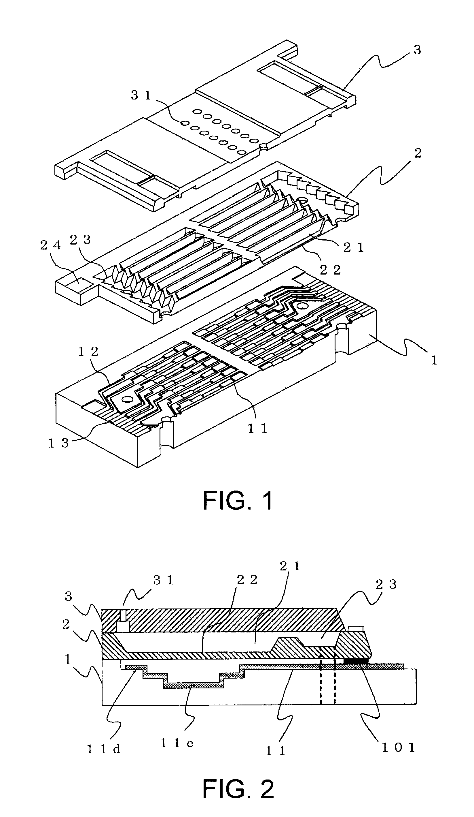
[0028]FIG. 1 is an exploded perspective view schematically showing an inkjet head (an example of a droplet ejecting head) according to a first embodiment of the invention. The inkjet head shown in FIG. 1 has a triple-layer structure including three substrates, an electrode glass substrate 1, a cavity substrate 2, and a nozzle wafer 3, bonded together. The cavity substrate 2 is bonded on the electrode glass substrate 1, and the nozzle wafer 3 is bonded on the cavity substrate 2. Hereinafter, structures of each substrate will be described.

[0029]The electrode glass substrate 1 is made of a glass substrate with a thickness of about 1 mm, for example. In particular, it is suitable to use a hard heat-resistant glass, such as a borosilicate glass, having a thermal expansion coefficient close to that of a silicon substrate as the cavity substrate 2. This is because, when the electrode glass substrate 1 and the cavity substrate 2 are anodically bonded together, the close thermal expansion co...

second embodiment

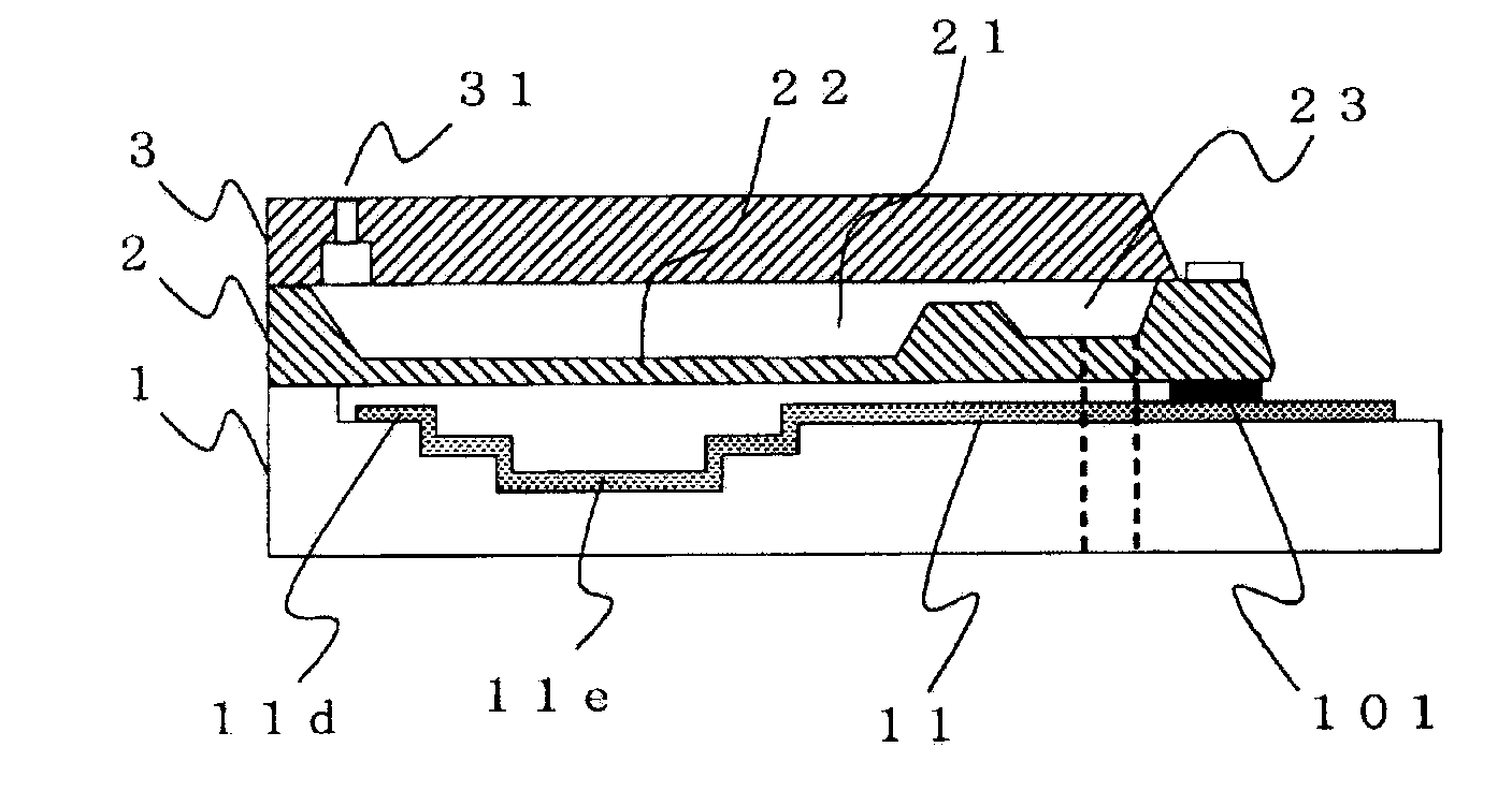
[0050]When pressure is applied to the ink by the electrostatic actuator (the vibration plate 22 and the individual electrode 11), it may be difficult to apply pressure having a waveform whose phase is delayed by 90 degrees from that of the residual vibration. However, pressure having a waveform approximating the waveform whose phase is delayed by 90 degrees from that of the residual vibration of the ink is applied to the ink, so that the residual vibration can be quickly suppressed. Note that in the second embodiment, the same numerals are given to the same functions and structures as those in the second embodiment.

[0051]FIG. 5 is a characteristic diagram showing an example of an applied voltage waveform of the electrostatic actuator according to the second embodiment of the invention. In the second embodiment, after a driving voltage for ejecting ink droplets is applied to the electrostatic actuator (the vibration plate 22 and the individual electrode 11), a vibration control volta...

third embodiment

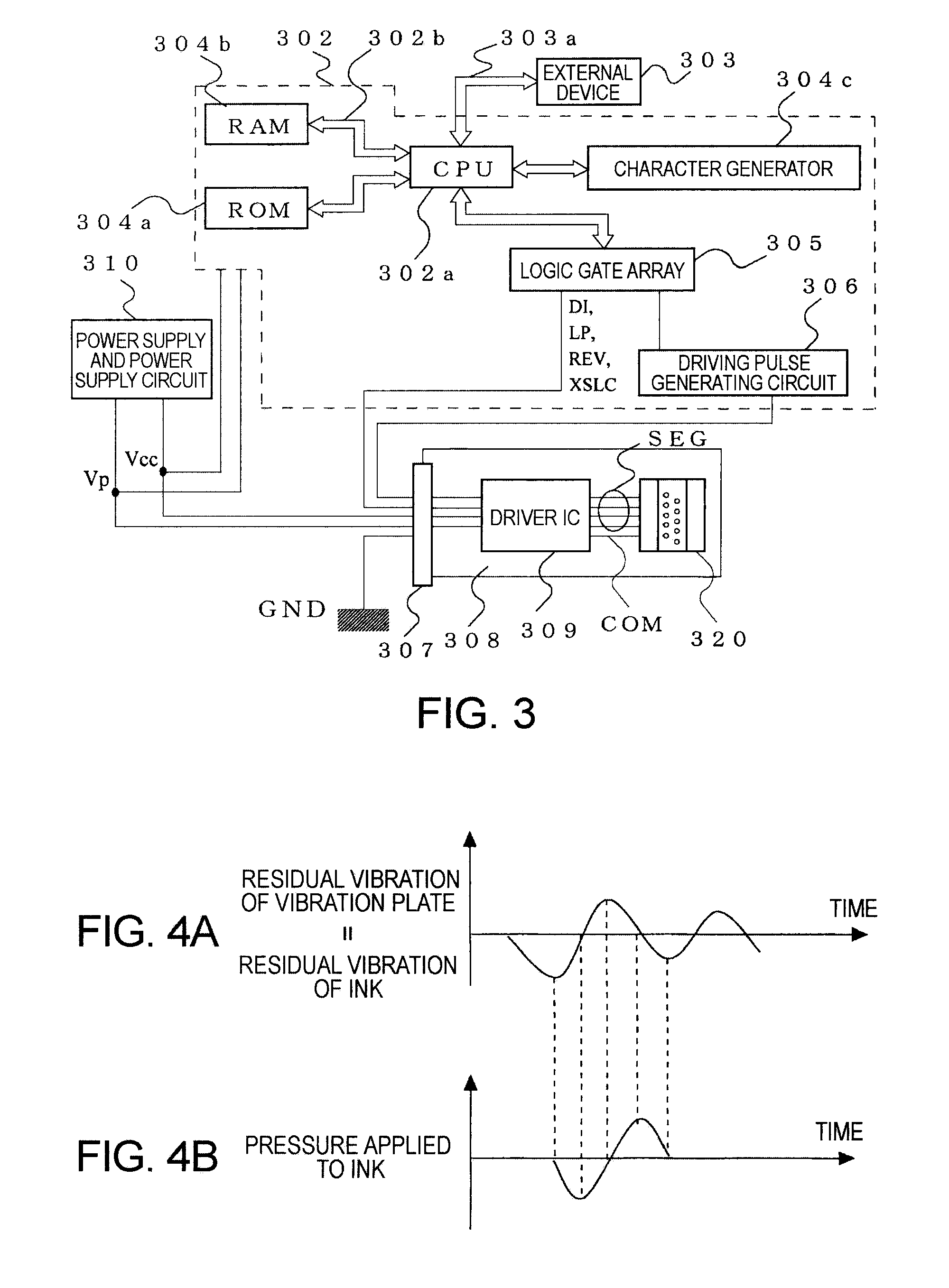
[0064]FIG. 8 shows a structure of an inkjet printer (an example of a droplet ejecting device) according to a third embodiment of the invention. The inkjet printer shown in FIG. 8 includes a platen 802 for feeding a recording sheet 801 in a sub-scanning direction Y, an inkjet head (not shown) whose ink nozzle faces confront the platen 802, a carriage 803 for reciprocating the inkjet head in a main-scanning direction X, and an ink tank 804 for supplying ink to each ink nozzle of the inkjet head. A nozzle cap 805 is disposed at a position deviated from the platen 802 in the main-scanning direction X, and the nozzle cap 805 is communicated with a waste ink recovery section 807 through an ink pump 806. As a structure of the inkjet head and a method for driving the same, those described in the first and the second embodiments can be employed.

[0065]In the third embodiment, an example is described in which the droplet ejecting head and the method for driving the same described in the first ...


PUM


Abstract

A method for driving a droplet ejecting head that includes a liquid pressure chamber communicating with a nozzle hole, and a pressure application unit applying pressure on liquid stored in the liquid pressure chamber for ejecting a droplet from the nozzle hole, includes applying on the liquid stored in the liquid pressure chamber pressure having a waveform whose phase is delayed by 90 degrees from a waveform of a residual vibration of the liquid by the pressure application unit after an ejection of the droplet from the nozzle hole.

Description

CROSS-REFERENCE TO RELATED APPLICATION[0001]1. Technical Field[0002]This application is based on and claims priority from Japanese Patent Application No. 2008-284526, filed on Nov. 5, 2008, the contents of which are incorporated herein by reference.BACKGROUND[0003]1. Technical Field[0004]The present invention relates to a method for driving a droplet ejecting head, and a droplet ejecting device driving the droplet ejecting head by using the method.[0005]2. Related Art[0006]As a droplet ejecting head used to eject droplets, an inkjet head mounted to an apparatus such as an inkjet recording apparatus is known. The inkjet head ejects ink in a liquid pressure chamber from nozzle holes by vibrationally applying pressure to the ink. At this time, vibration remains in the ink in the liquid pressure chamber even after the ejection of the ink. Therefore, ejecting operations performed after the vibration is stopped and during the vibration have different ejecting characteristics (quantity and...

Claims


Application Information

Patent Timeline
Patent Type & Authority Applications(United States)
IPC IPC(8): B41J29/38B41J2/045
CPCB41J2/04578B41J2/04588
Inventor SANO, AKIRA
Owner SEIKO EPSON CORP
Why Eureka
Try Eureka