Eureka AIR delivers breakthrough ideas for toughest innovation challenges, trusted by R&D personnel around the world.

Optical member unit, lighting device for display, display, and television receiver

Active Publication Date: 2010-05-06
SHARP KK
View PDF9 Cites 8 Cited by
  • Summary
  • Abstract
  • Description
  • Claims
  • Application Information

AI Technical Summary

Benefits of technology

[0009]Thereby, the occurrence of moire caused by the interference between the arrangement of pixels in the display panel and the arrangement of the unit lenses can be prevented by the inclined posture supporting member, while using the optical member comprising the lens portion wherein the unit lenses are arranged in parallel with the edge. Accordingly, a measure can be taken against moire without using a particular optical member in which the unit lenses are arranged while being inclined relative to the edge.
[0012](2) The protrusion is provided in the side of the positioning member. Thereby, the manufacture can be simplified in comparison with the case of temporarily providing the protrusion in the side of the optical member.
[0014](4) The protrusion is made of a rubber material. Thereby, even when heat expansion and heat contraction occurs to the optical member, the protrusion made of a rubber material elastically deforms so as to allow the optical member to expand and contract. This makes it difficult for the optical member to sag.
[0015](5) The positioning member is made of synthetic resin, and integrally formed with the protrusion. Thereby, cost reduction can be expected in comparison with the case of providing the protrusion as a body separated from the positioning member.
[0018](8) The positioning member is composed of a receiving member for receiving the optical member on the back side and a holding member for holding the optical member from the front side, wherein the protrusion is provided in the side of the receiving member. With such configuration, when fitting the optical member to the positioning member, the supporting posture of the optical member can be determined at the same time of putting the optical member onto the receiving member, and thereby developing good workability.
[0020]The present invention provides an optical member unit in which moire can be avoided while using an optical member having the unit lenses arranged in parallel with the edge.

Problems solved by technology

The optical member is constituted normally by laminating multiple of such as a diffuser plate, a diffuser sheet, a lens sheet, and a brightness enhancing sheet, however, with such configuration, the emitted light is diffused easily in a direction not used for display, resulting in undesirable light use efficiency.

Method used


Image

  • Optical member unit, lighting device for display, display, and television receiver
  • Optical member unit, lighting device for display, display, and television receiver
  • Optical member unit, lighting device for display, display, and television receiver

Examples


embodiment 1

[0043]Embodiment 1 of the present invention is explained in reference to FIGS. 1 to 12. In Embodiment 1, a liquid crystal display device D is exemplified as a display.

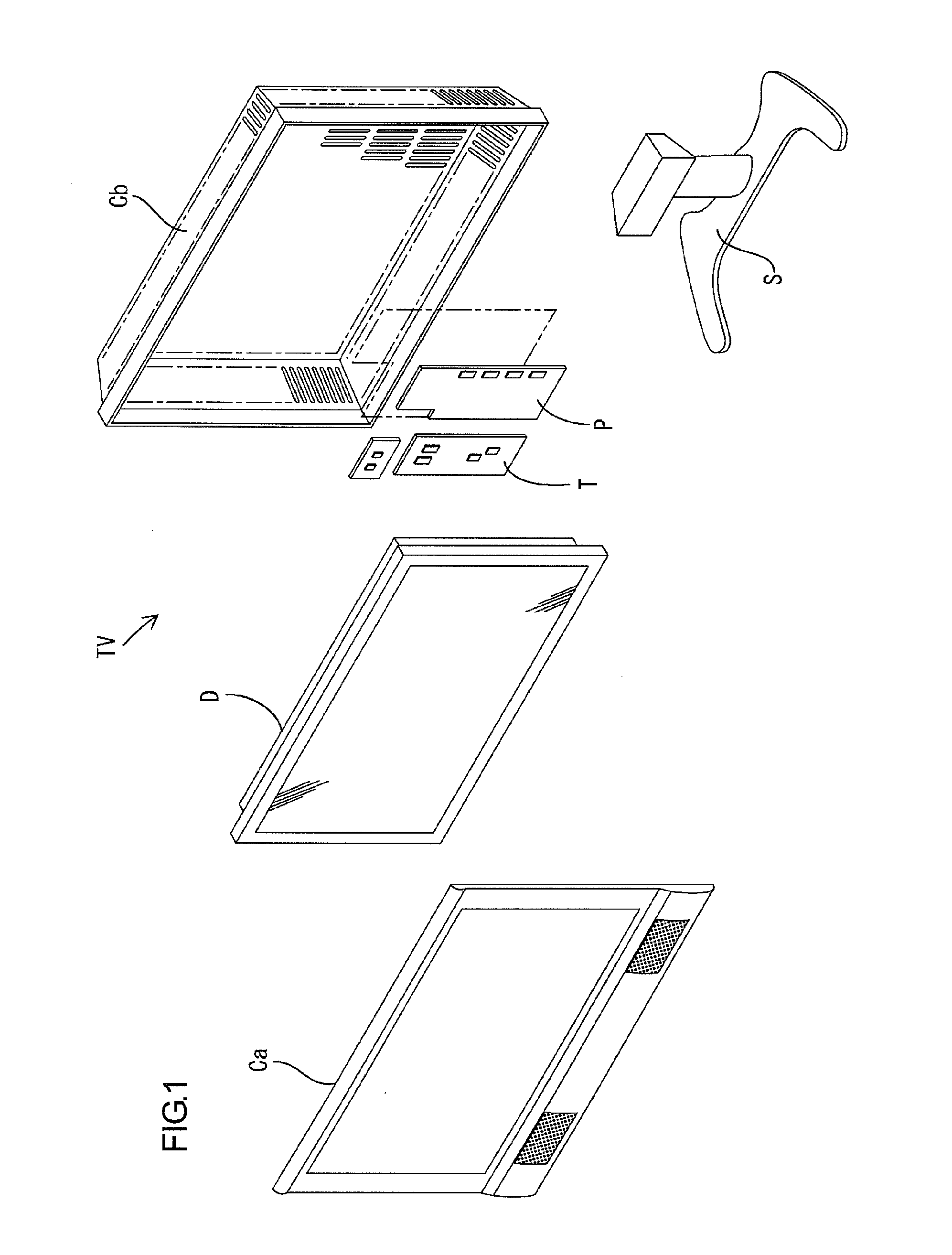
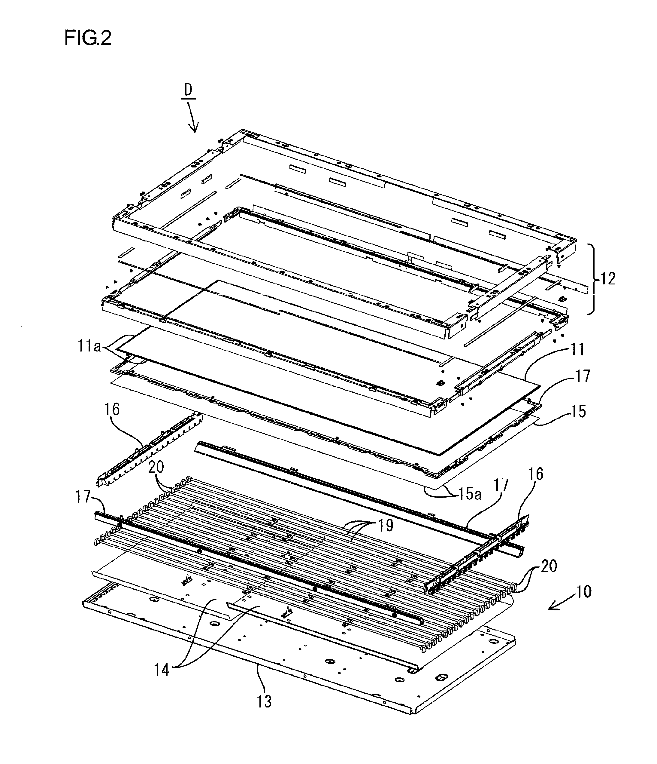
[0044]The liquid crystal display device D has a laterally long square shape on the whole, and is constituted by, as shown in FIG. 2, holding a liquid crystal panel 11 as a display panel and a backlight 10 as an external light source (lighting device) of the liquid crystal panel 11 into a fitted-state by a bezel 12 covering from the front side. The liquid crystal panel 11 is disposed in the front side of the backlight 10, and irradiated by the backlight 10 from the rear surface side. The liquid crystal display device D can be applied to a television receiver TV. The television receiver TV is constituted by comprising, as shown in FIG. 1, the liquid crystal display device D, both front and rear cabinets Ca and Cb housing the liquid crystal display device D in a manner so as to hold it from both sides, a power source P, a...

embodiment 2

[0079]Embodiment 2 of the present invention is explained in reference to FIG. 13 or 14. In Embodiment 2, such as the arranging position of a protrusion 34 is changed. Additionally, in Embodiment 2, a repetitive description of the structure, action, and effect similar to those in the above Embodiment 1 is omitted.

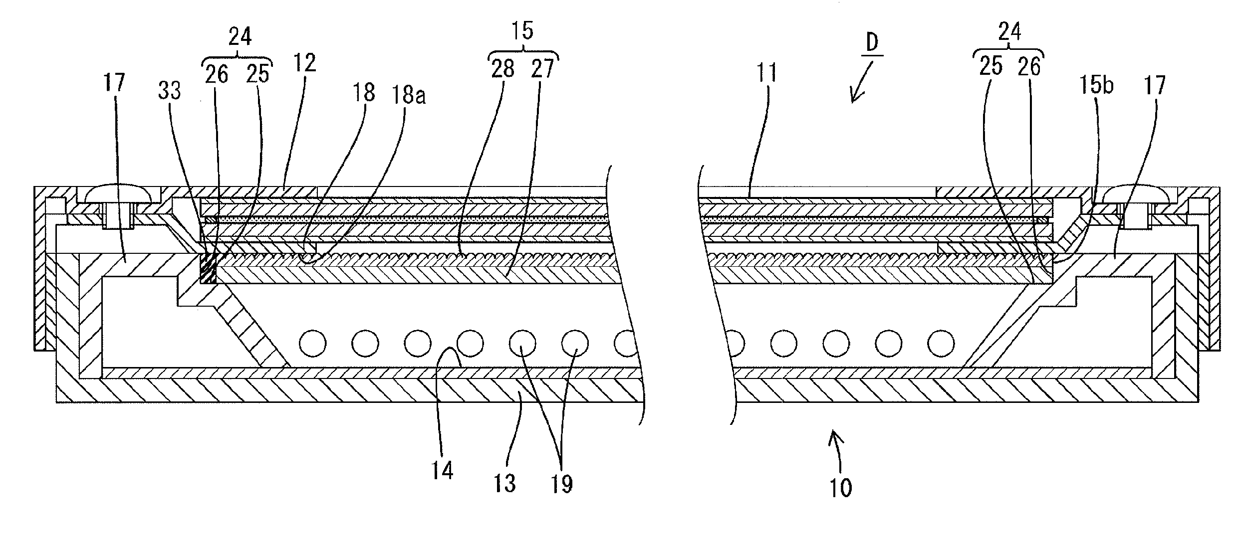
[0080]As shown in FIG. 13, the protrusion 34 constituting the inclined posture supporting member is respectively provided in all of both lamp holders 16 and both holders 17 which compose the receiving member. In details, in the holder 17 disposed in the vertically lower side in use state, the protrusion 34 is placed in the vicinity of the right end position shown in FIG. 13 in the receiving member 24, while in the holder 17 disposed in the vertically upper side, the protrusion 34 is placed in the vicinity of the left end position in the same figure in the receiving member 24. On the other hand, in the lamp holder 16 disposed in the right side in the same figure in use state,...

embodiment 3

[0083]Embodiment 3 of the present invention is explained in reference to FIG. 15 or 16. In Embodiment 3, such as the arranging position of a protrusion 35 is changed. In Embodiment 3, a repetitive description of the structure, action, and effect similar to those in the above Embodiment 1 is omitted.

[0084]As shown in FIG. 15, the protrusion 35 constituting the inclined posture supporting member is respectively provided in both lamp holders 16 disposed in both sides in the receiving member in use state. In details, in the lamp holder 16 disposed in the right side in the same figure in use state, the protrusion 35 is placed in the vicinity of the vertically upper side of the receiving member 21, while in the lamp holder 16 disposed in the left side in the same figure, the protrusion 35 is placed in the vertically lower side in the receiving member 21. When the optical member 15 is put on, as shown in FIG. 16, the corresponding protrusions 35 respectively abut the end surface 15b in the...


PUM


Abstract

An optical member 15 is constituted by sticking a lens sheet 28 capable of transmitting light irradiated toward a liquid crystal panel 11 and a diffuser sheet 27 together. The lens sheet 28 is provided with a lens portion 30 having a large number of unit lenses 29 aligned on the front surface, while on the rear surface, provided with a reflecting layer 32 having an opening 31 corresponding to the lens portion 30. The optical member 15 is received on the backside by receiving members 21 and 24 provided respectively in a holder 17 and a lamp holder 16, while being held from the front by a frame 18. A protrusion 33 is provided in the receiving member 24 in the holder 17, which supports the optical member 15 in a posture so that the edge 15a of the optical member 15 and the arrangement of the unit lenses 29 are inclined relatively to the arrangement of the pixel electrodes PE in the liquid crystal panel 11, by abutting an outer circumferential end surface 15b in the optical member 15.

Description

FIELD OF THE INVENTION[0001]The present invention relates to an optical member unit, a lighting device for display, a display, and a television receiver.BACKGROUND ART[0002]A liquid crystal display device is composed of a liquid crystal panel as a display panel and a backlight as an external light source placed in the rear surface side of the liquid crystal panel. Among these, the backlight comprises a plurality of cold cathode fluorescent lamps as a linear light source and an optical member for converting a linear light emitted from each cold cathode fluorescent lamp into a surface light. The optical member is constituted normally by laminating multiple of such as a diffuser plate, a diffuser sheet, a lens sheet, and a brightness enhancing sheet, however, with such configuration, the emitted light is diffused easily in a direction not used for display, resulting in undesirable light use efficiency.[0003]Considering the foregoing, the invention disclosed in Patent Literature 1 has b...

Claims


Application Information

Patent Timeline
IPC IPC(8): G02F1/13357G02B3/08G09F13/04
CPCG02F1/133604G02F1/133608G02F2001/133322G02F2001/133607G02F2201/34G02F1/133322G02F1/133607
Inventor KAMADA, KENTARO
Owner SHARP KK
Why Eureka
Eureka Blog
Learn More