
Polarizing lens

a polarizing lens and lens body technology, applied in the field of polarizing lenses, can solve problems such as poor waterproofness, and achieve the effect of significantly improving waterproofness

Inactive Publication Date: 2010-05-06
NEWTON CO LTD
View PDF5 Cites 21 Cited by
  • Summary
  • Abstract
  • Description
  • Claims
  • Application Information

AI Technical Summary

Benefits of technology

[0009]Since a mixture of an epoxy resin and an acid anhydride is used as an adhesive, bonding of polyvinyl alcohol constituting the polarizing thin film and the protective film can be ensured. In particular, elusion caused by water of polyvinyl alcohol constituting the polarizing thin film can be prevented, whereby waterproofness is improved. The reason therefor is considered to be as follows. The acid anhydride causes the epoxy resin to be hardened and forms a chemical bonding with the hydroxyl group of the polyvinyl alcohol, and undergoes three-dimensional hardening.
[0017]According to the polarizing lens of the invention, due to the use of a mixture of an epoxy resin and an acid anhydride as an adhesive for the polarizing plate, bonding of polyvinyl alcohol constituting the polarizing thin film and the protective film can be ensured. In particular, elusion caused by water of polyvinyl alcohol constituting the polarizing plate can be prevented, enabling waterproofness to be significantly improved.

Problems solved by technology

The above-mentioned conventional polarizing lens has the disadvantage that waterproofness is not necessarily good.

Method used


Image

  • Polarizing lens
  • Polarizing lens

Examples


example 1

[0033]In the adhesive, triglycidyl-p-aminophenol (“Epicoat 630” manufactured by Japan Epoxy Resins Co., Ltd.) was used as the epoxy resin. As the acid anhydride, maleic anhydride (Wako Pure Chemical Industries, Ltd.) was used. The maleic anhydride was used in an amount of 105 parts by weight relative to 100 parts by weight of the epoxy resin (1.05 in terms of equivalent ratio (ratio of the acid anhydride equivalent to the epoxy equivalent)).

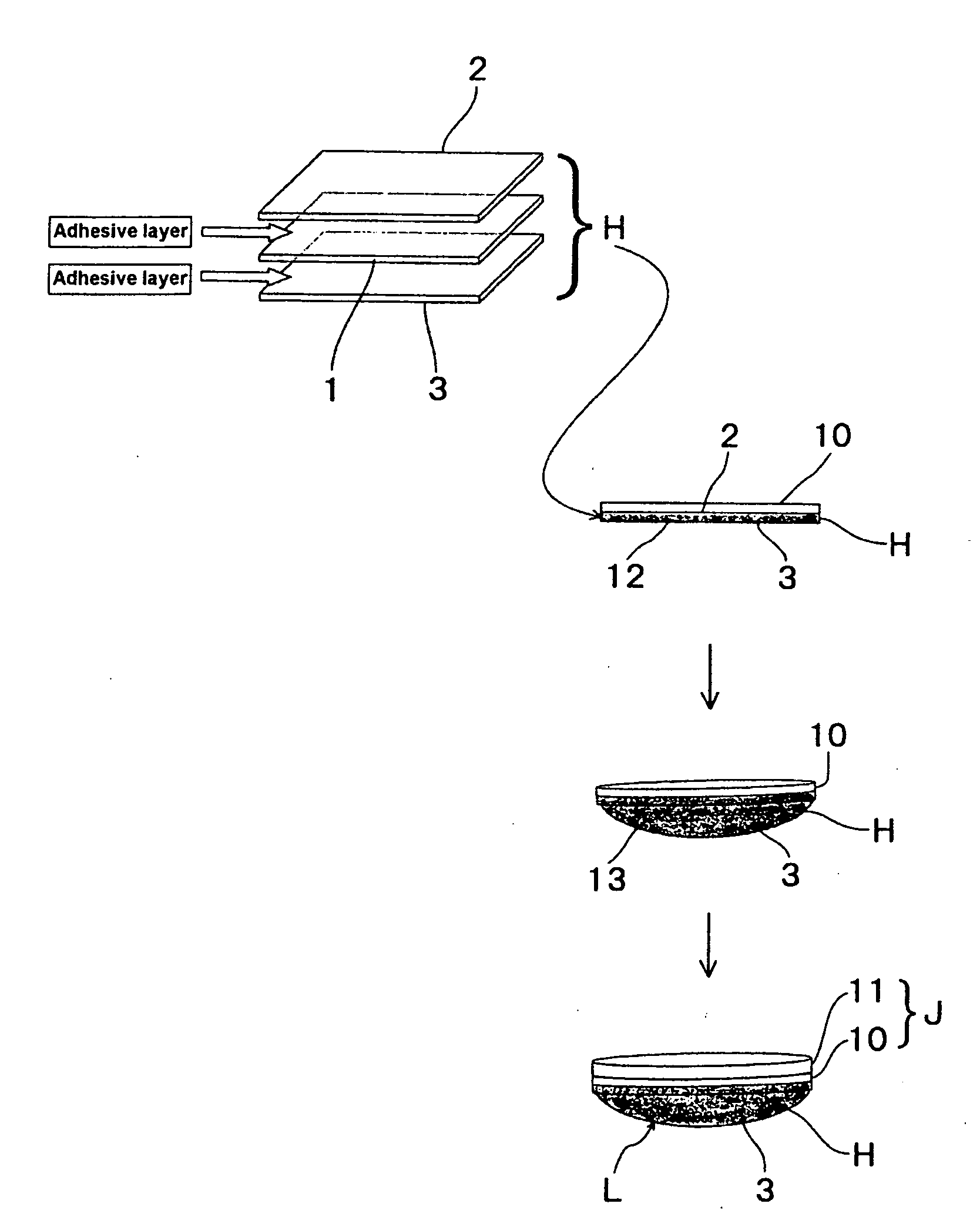
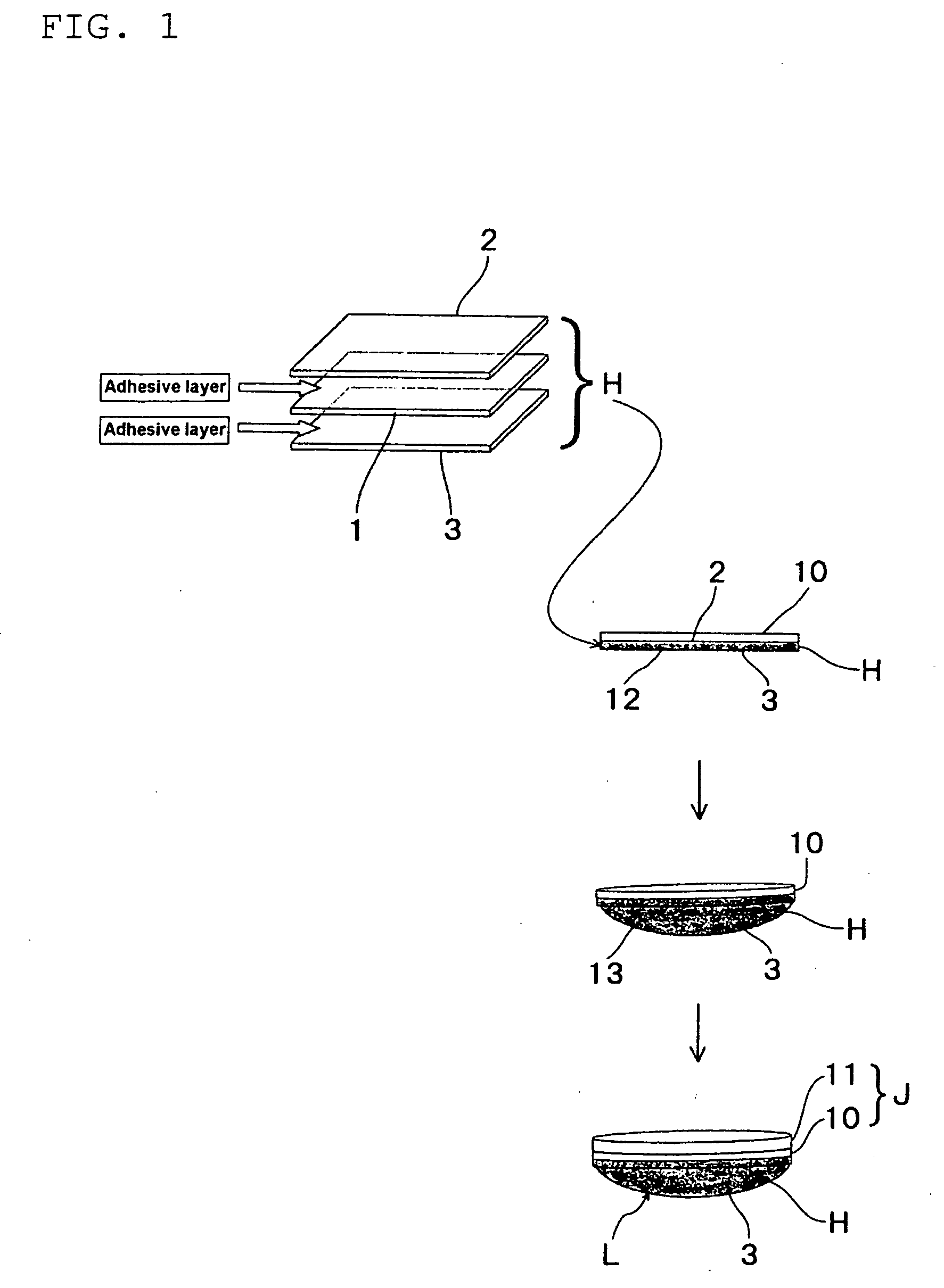
[0034]Then, using this adhesive, at a hardening temperature of 100° C. and a hardening time of 24 hours, the protective films 2 and 3 were adhered to the both sides of the polarizing thin film 1.

example 2

[0035]In the adhesive, polyglycol diglycidyl ether (“YED205” manufactured by Japan Epoxy Resins Co., Ltd.) was used as the epoxy resin. As the acid anhydride, maleicanhydride (Wako Pure Chemical Industries, Ltd.) was used. The maleic anhydride was used in an amount of 35 parts by weight relative to 100 parts by weight of the epoxy resin (0.5 in terms of equivalent ratio (ratio of the acid anhydride equivalent to the epoxy equivalent)).

[0036]Then, using this adhesive, at a hardening temperature of 100° C. and for a hardening time of 24 hours, the protective films 2 and 3 were adhered to the both sides of the polarizing thin film 1.

[0037]The polarizing plates H according to these Examples and Comparative Examples were subjected to a water-proof test. In Comparative Examples, as the polarizing thin film 1 and the protective films 2 and 3, the same polarizing thin film 1 and the protective films 2 and 3 as those in the above-mentioned Examples were used, and the composition and the hard...


PUM

PropertyMeasurementUnit
temperatureaaaaaaaaaa
thicknessaaaaaaaaaa

Abstract

In a polarizing lens L which is obtained by a process in which a polarizing plate H formed by bonding protective films 2 and 3 to the both sides of a polarizing thin film 1 of polyvinyl alcohol, a thermoplastic resin film 10 is bonded to one side of the polarizing plate H with an adhesive or a sticking agent, the thermoplastic resin film 10 is subjected to curved molding such that this thermoplastic resin film 10 is positioned on the concave surface side, and a thermoplastic resin molded layer 11 formed of the same resin as that for the thermoplastic resin film 10 is laminated on the concave surface of this polarizing plate H, the protective films 2 and 3 are bonded to both sides of the polarizing thin film 1 with an adhesive, and a mixture of an epoxy resin and an acid anhydride is used as the adhesive.

Description

TECHNICAL FIELD[0001]The invention relates to a polarizing lens used in glare-proof sunglasses, goggles, or the like.BACKGROUND ART[0002]In respect to the above-mentioned polarizing lens, for example, a polarizing lens has conventionally been known which is obtained by subjecting to curved molding a polarizing plate formed by bonding protective films formed of acetyl cellulose both sides of a polarizing thin film made of polyvinyl alcohol, and laminating a polycarbonate resin layer on the concave surface of the polarizing plate. Regarding this polarizing lens, for example, the polarizing plate has a structure in which protective films are bonded to the both sides of a polarizing thin film with adhesive (see JP-A-2002-90529, for example).[0003]Patent Document 1: JP-A-2002-90529[0004]The above-mentioned conventional polarizing lens has the disadvantage that waterproofness is not necessarily good. Specifically, if immersed in water, the polarizing thin film and the protective film may ...

Claims


Application Information

Patent Timeline
Patent Type & Authority Applications(United States)
IPC IPC(8): G02B1/08
CPCB29D11/00634B29D11/0073G02B1/041G02B5/3025G02C7/12C08L63/00C08L69/00Y10T428/31511
Inventor SASAKI, HIDEYUKISAKURABA, YOSHIYUKIITO, MASAKIFUJITA, TAKAYUKI
Owner NEWTON CO LTD
Learn More