Connector

Active Publication Date: 2010-05-06
SUMITOMO WIRING SYST LTD
View PDF6 Cites 21 Cited by
  • Summary
  • Abstract
  • Description
  • Claims
  • Application Information

AI Technical Summary

Benefits of technology

[0009]A further object of the invention is to make it difficul

Problems solved by technology

The tapered guide causes the reinforcing rib to be smaller and thus reduces the strength of the reinforcing rib.
However, a slight gap may be formed between the

Method used


Image

  • Connector
  • Connector
  • Connector

Examples


Embodiment Construction

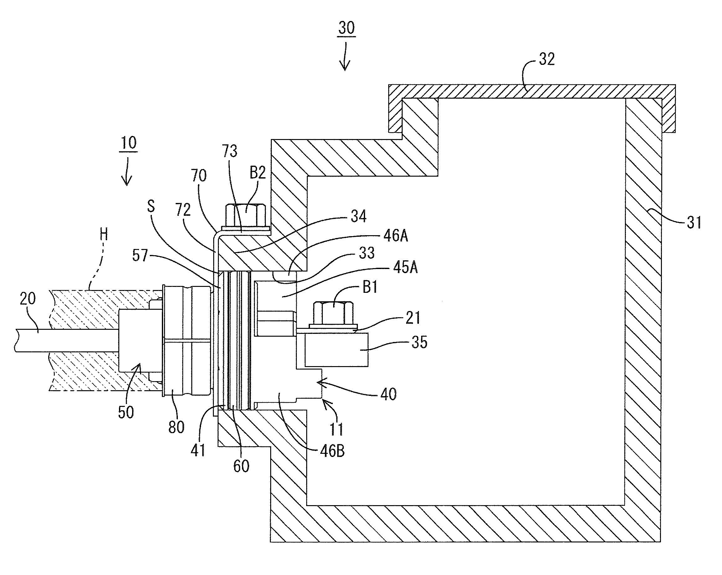
[0035]A connector in accordance with the invention is identified generally by the numeral 10 in FIGS. 1 through 13. The connector 10 is for an apparatus and is mounted on an inverter of an electric car. More particularly, the connector 10 is used to supply the inverter with electric power from a battery (not shown). Therefore the connector 10 for the apparatus is connected to one end of an electric wire 20 and the other end of the electric wire 20 is connected to the battery. The inverter is not shown in the drawings, but is accommodated inside a case 30 that is made of a metal and has a shielding function.

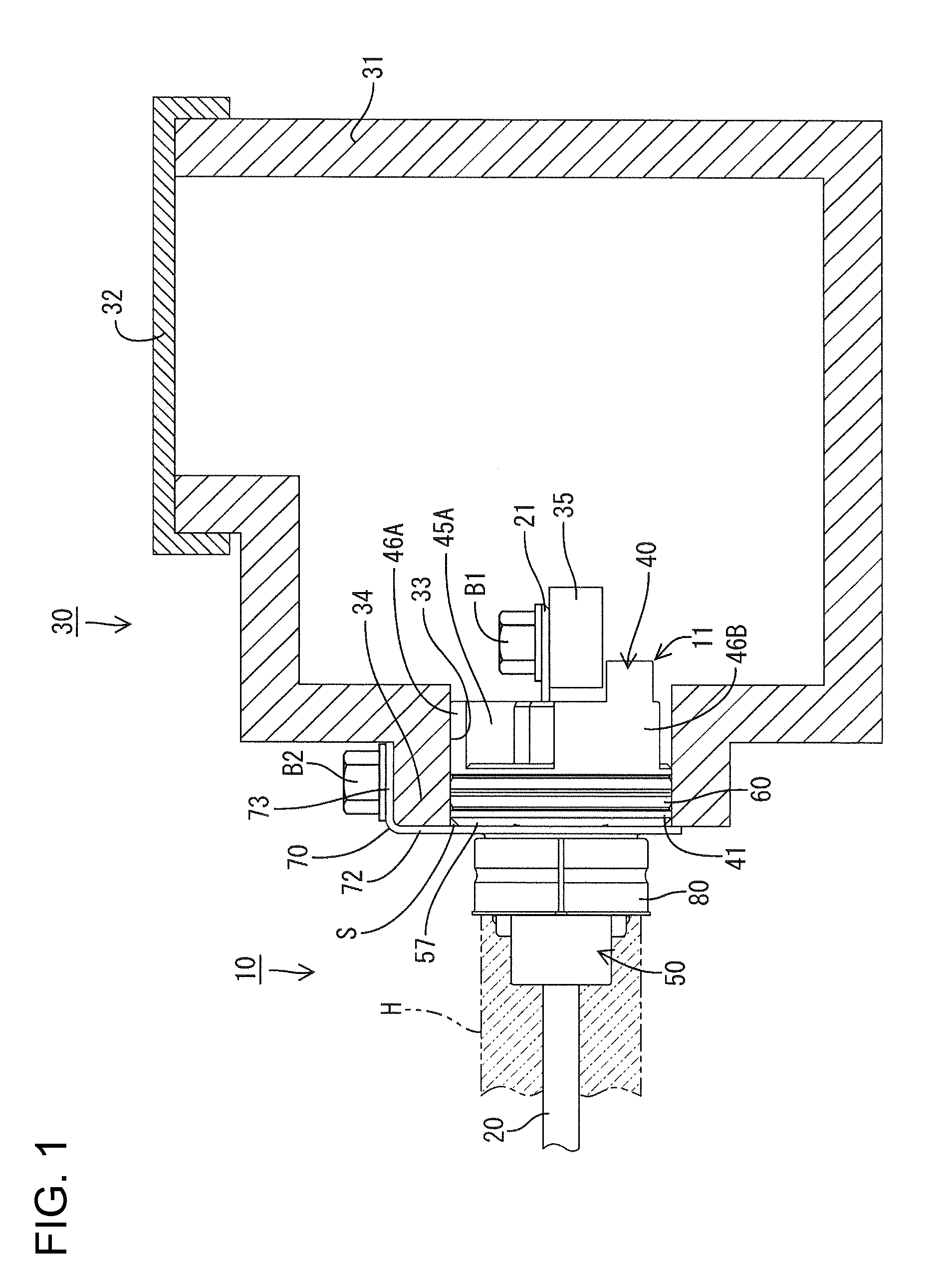
[0036]As shown in FIG. 1, the case 30 has a main body 31 with an upper opening and an upper cover 32 that closes the upper opening of the main body 31. A mounting hole 33 penetrates through a side wall of the main body 31 and through a fit-in tubular part 34 that projects out from an outer surface of the main body 31.

[0037]A terminal base 35 is disposed inside the case 30. The con...


PUM


Abstract

A connector (10) for an apparatus includes a housing (11) having a fit-in part (41) to be fit in a mounting hole (33) that penetrates through a case (30) of the apparatus. Tubular terminal insertion parts (42), penetrating through the fit-in part (41) and can receive a terminal fitting (21) connected with an end of a wire (20). Guide ribs (46A-46C) project from the fit-in part (41) into the case (30) and are spaced apart around an inner peripheral surface of the mounting hole (33). Reinforcing ribs (45A-45D) projecting into the case (30) Each reinforcing rib (45A-45D) and connects a side edge of a guide rib (46A-46C) to a peripheral surface of a terminal insertion part (42).

Description

BACKGROUND OF THE INVENTION[0001]1. Field of the Invention[0002]The invention relates to a connector to be mounted on a case of an apparatus.[0003]2. Description of the Related Art[0004]Japanese Patent Application Laid-Open No. 2003-179381 discloses a connector to be mounted on a case of an apparatus, such as an inverter. A mounting hole penetrates the case of the apparatus and the connector has a housing with a fit-in part that can be fit in the mounting hole. A tubular terminal insertion part penetrates through the fit-in part and a terminal connected to the end of an electric wire is inserted through the terminal insertion part. A reinforcing rib is connected with the peripheral surface of the terminal insertion part and projects into the case to prevent the terminal insertion part from inclining. A tapered guide is formed on a side edge of the reinforcing rib opposed to the inner peripheral surface of the mounting hole and slidingly contacts the inner peripheral surface of the m...

Claims


Application Information

Patent Timeline
IPC IPC(8): H01R13/52H01R13/40H01R13/648
CPCH01R13/5208H01R13/5227H01R13/629H01R13/648H01R13/74
Inventor YONG, ZHU
Owner SUMITOMO WIRING SYST LTD
Why Eureka
Try Eureka