Generation of a composite mitigation signalwith a desired spectral energy distrubution

a composite mitigation and spectral energy distrubution technology, applied in the field of frequency translation circuits, can solve the problems of prohibitively expensive and complex, inability to suitably attenuate off-channel spurious signals without filters, and undesired spurious responses

Active Publication Date: 2010-05-06
MOTOROLA SOLUTIONS INC
View PDF4 Cites 10 Cited by
  • Summary
  • Abstract
  • Description
  • Claims
  • Application Information

AI Technical Summary

Problems solved by technology

However, if the frequencies of the off-channel spurious signals are close to the desired on-channel frequencies of the input signal 104, the filters necessary to suitably attenuate the off-channel spurious signals without adversely attenuating the input signal 104 become prohibitively expensive and complex due to the very high quality factor (Q) that is required of the filters.
Since the fundamental frequency 604-1 and the lower order harmonics 604-3-604-9 generally con

Method used


Image

  • Generation of a composite mitigation signalwith a desired spectral energy distrubution
  • Generation of a composite mitigation signalwith a desired spectral energy distrubution
  • Generation of a composite mitigation signalwith a desired spectral energy distrubution

Examples


Embodiment Construction

[0026]While the specification concludes with claims defining features of the invention that are regarded as novel, it is believed that the invention will be better understood from a consideration of the description in conjunction with the drawings. As required, detailed embodiments are disclosed herein; however, it is to be understood that the disclosed embodiments are merely exemplary, and the invention can be embodied in various forms. Therefore, specific structural and functional details disclosed herein are not to be interpreted as limiting, but merely as a basis for the claims and as a representative basis for teaching one skilled in the art to variously employ the present invention in virtually any appropriately detailed structure. Further, the terms and phrases used herein are not intended to be limiting but rather to provide an understandable description of the invention.

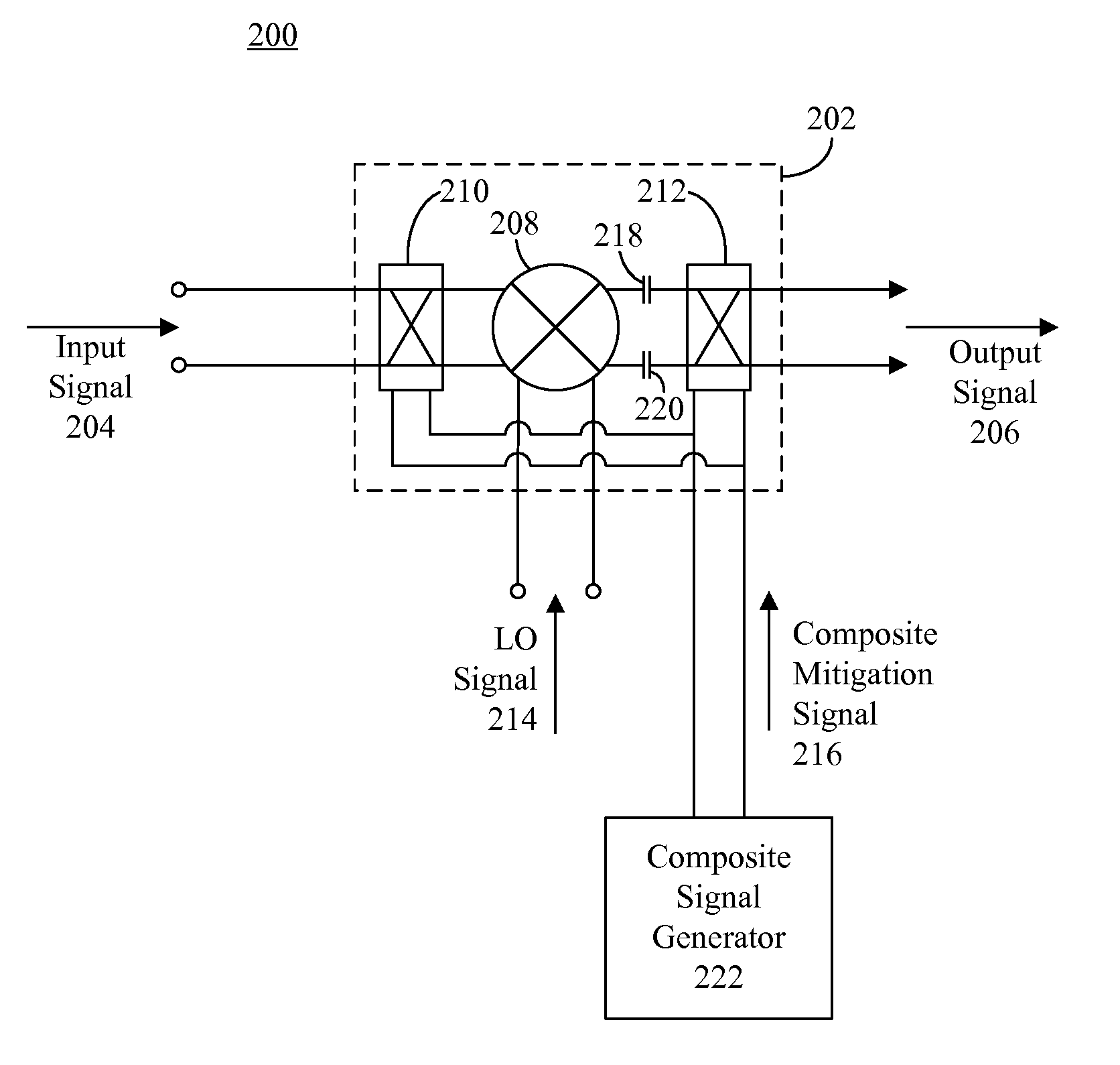
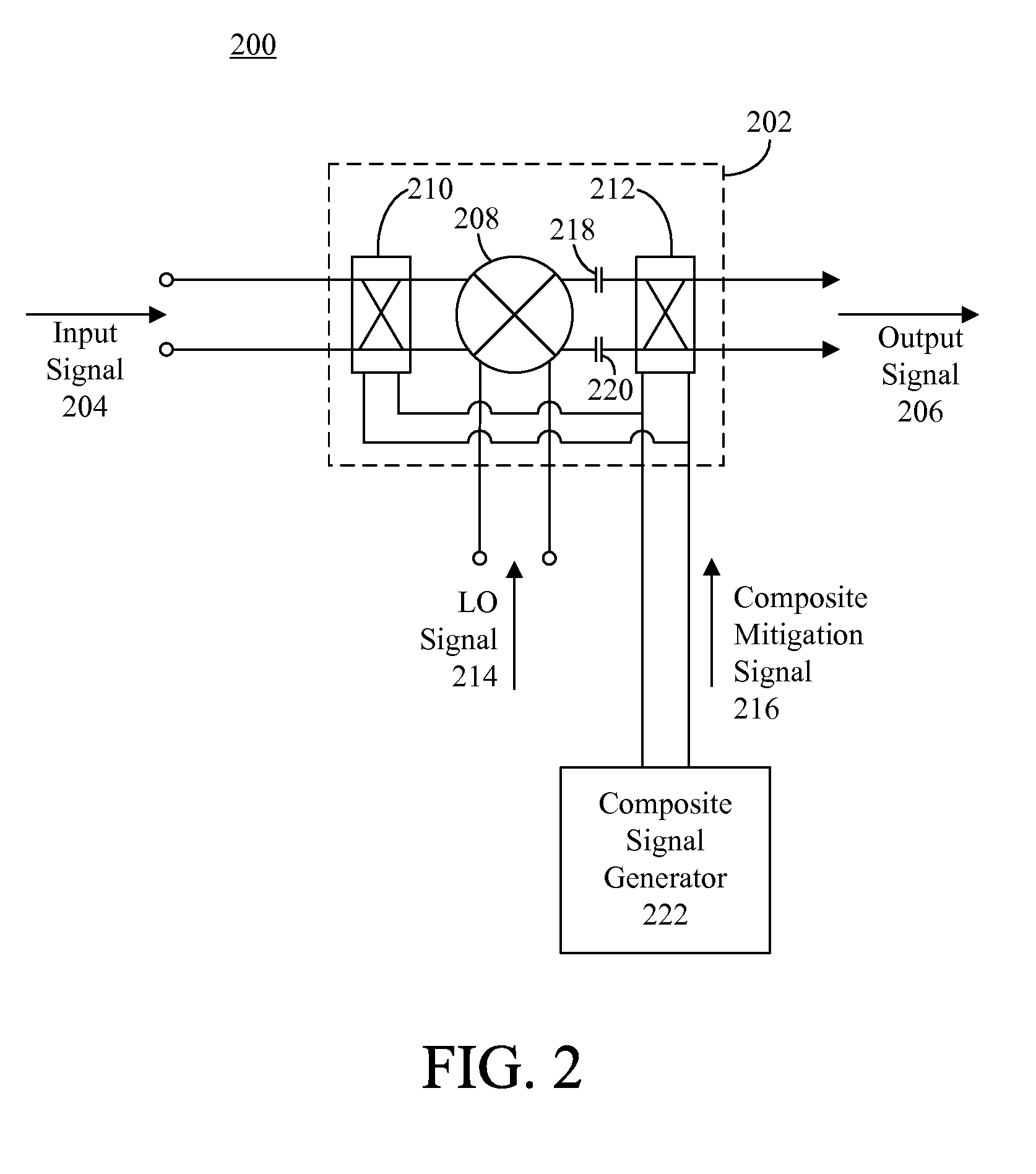
[0027]FIG. 2 depicts a frequency translation circuit 200 that is useful for understanding arrangements de...


PUM


Abstract

A method (1100, 1200) of generating a composite mitigation signal (216, 902, 1002) is presented. The composite mitigation signal includes an odd integer (N) of transitions (310, 312) between a first amplitude and a second amplitude of the composite mitigation signal. Successive sets of the transition bursts are separated by a desired phase delay or time delay (330), or such separations are defined by a base signal (416) having a frequency equal to a fundamental frequency of the composite mitigation signal. The composite signal generators (222, 900, 1000) that generate the composite mitigation signal are also presented.

Description

TECHNICAL FIELD [0001]The present application generally relates to frequency translation circuits and, more particularly, to frequency translation circuits which include dynamically matched mixers.BACKGROUND [0002]Modern radio frequency (RF) receivers oftentimes include a frequency translation circuit that receives RF signals from a RF front end, translates the RF signals into a lower frequency band, and outputs the lower frequency signals for further processing. For instance, a frequency translation circuit may be implemented to translate RF input signals to intermediate frequency (IF) signals. Frequency translation circuits also may be used in RF transmitters to translate lower frequency signals, such as IF signals, to higher frequency bands, for example to generate RF output signals.[0003]An example of a frequency translation circuit 100 is depicted in FIG. 1. The frequency translation circuit 100 commonly may include a dynamically matched mixing stage (hereinafter “mixing stage”...

Claims


Application Information

Patent Timeline
IPC IPC(8): H04B1/26
CPCH04L25/4902
Inventor RUELKE, CHARLES R.NAGARAJ, GEETHA B.SYED, SHAFIULLAH
Owner MOTOROLA SOLUTIONS INC
Why Eureka
Try Eureka