Apparatus and method for the identification of fake fingerprints

a fingerprint scanner and fake fingerprint technology, applied in the field of fake fingerprint scanners, can solve the problems of limiting the analysis of skin electrical signals to a fixed electrical frequency, not addressing the issue, and large skin area of fingers or similar areas, and achieve the effect of improving the identification of fake fingerprints and low-cost production

Inactive Publication Date: 2010-05-06
CROSS MATCH TECH
View PDF12 Cites 138 Cited by
  • Summary
  • Abstract
  • Description
  • Claims
  • Application Information

AI Technical Summary

Benefits of technology

[0010]It is a feature of the present invention to provide improved identification of fake fingerprints in a multiple fingerprint scanner using electrodes for liveness detection, especially in layouts or arran

Problems solved by technology

Such patents do not describe use of transparent electrodes in an optical fingerprint sensor, and limit their analysis of skin electrical signals to a fixed electrical frequency, and lithographic technology for fabricating the electrodes that is not scalable to large platen sizes capable of capturing surface topology images from two fingers, four fingers, or entire palm or hand.
Further, they only consider the case of electrode arrangements for a single-finger scanner, and electrodes and electronics that require the platen to be fixed (e.g., non-removable) as well as require the skin to be in direct contact with the electrodes.
Although the prior art discussed above describes the use of electrodes for impedance-based liveness detection by incorporation of transparent electrodes in a single-finger optical fingerprint scanner, such prior art does not address th

Method used


Image

  • Apparatus and method for the identification of fake fingerprints
  • Apparatus and method for the identification of fake fingerprints
  • Apparatus and method for the identification of fake fingerprints

Examples


Embodiment Construction

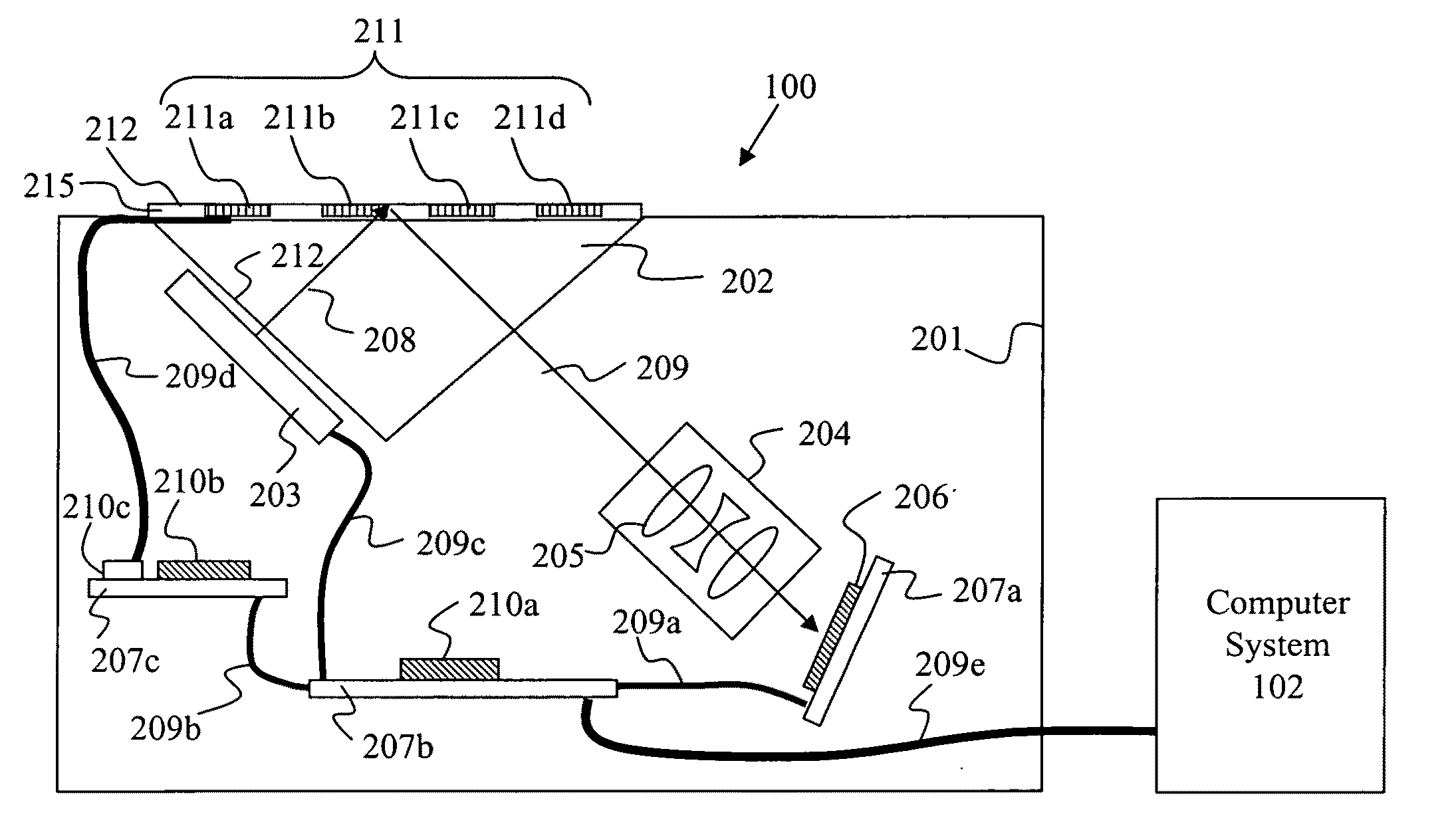
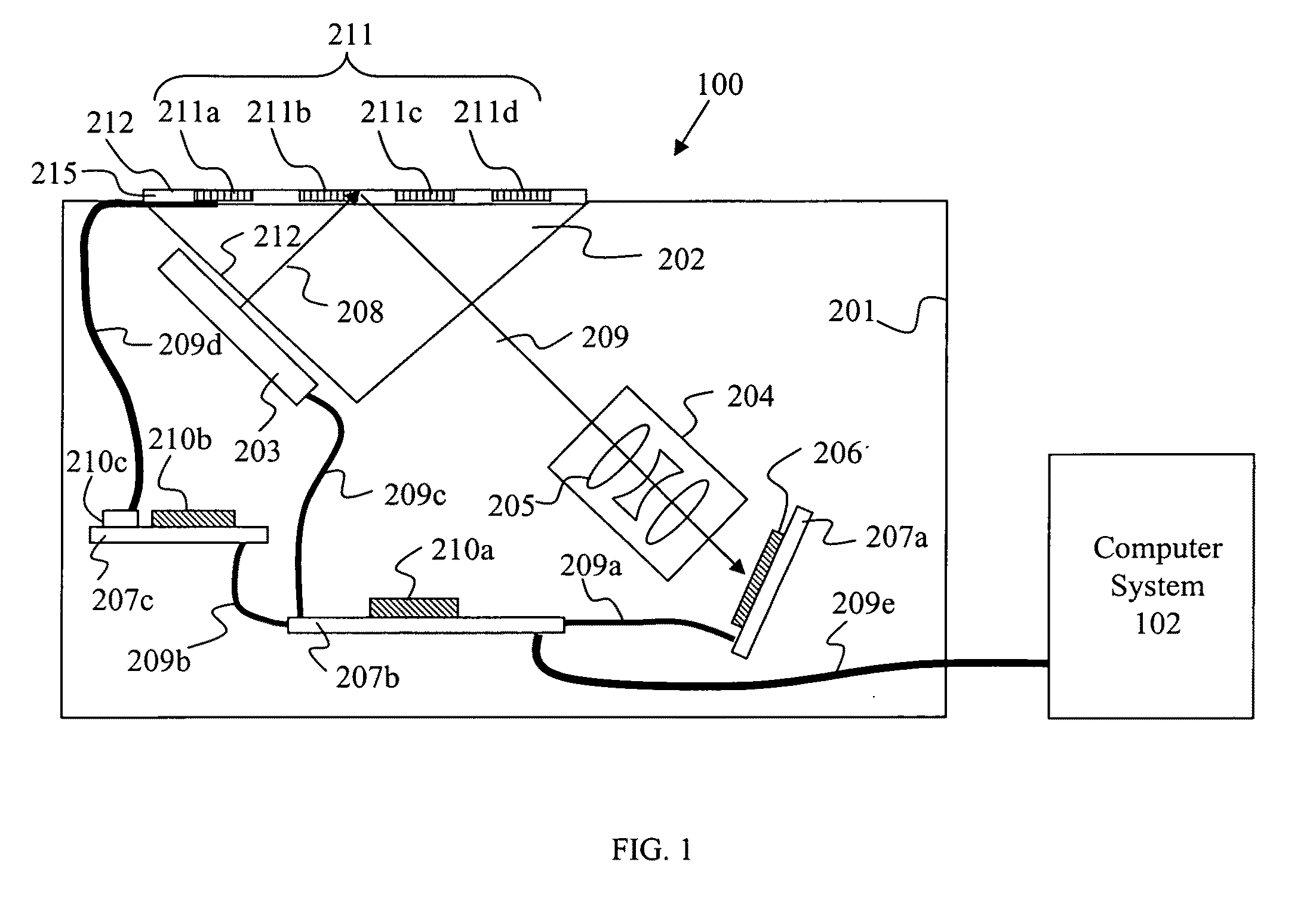
[0053]Referring to FIG. 1, an apparatus 100 for capturing fingerprints for one finger or multiple fingers of a hand is shown. Multiple electrodes are provided in or upon a platen 212 located on a housing 201 in which the platen is sized for capture of an image of one or a desired number of fingers. Housing 201 has an illumination source 203 for sending light through one facet 212 of a prism 202 that is substantially transparent at the wavelength of light source operation. Light (denoted by ray 208) from the illumination source strikes platen 212 and reflected light (denoted as ray 209) then propagates through an objective lens 204 (composed of one or more optical imaging elements 205) which focuses the reflected light onto two-dimensional (2-D) sensor or detector 206. The reflected light represents an image of the surface topology of the skin or the finger(s) presented to platen 212 at or about the fingertips as typical of fingerprints. However, the present invention is not restrict...


PUM


Abstract

An apparatus for identifying fake fingerprints has electrodes disposed along a platen surface of a fingerprint scanner and whether or not the skin of one or more fingers presented to the surface are real and alive is determined in accordance with analysis of electrical signals received from the electrodes. Electronics of the apparatus determines one or more liveness parameter(s) in accordance with signals received from electrodes. Information from an image of the fingerprint may be used to select which electrode signals to use for liveness detection. To further confirm the presence of a live finger(s), additional liveness parameter(s) of the pulse and/or temperature may also be sensed. The skin may be one of in contact with the platen of the fingerprint scanner, separated from direct contact with the platen's electrodes by an insulating layer or a pad, or not in physical contact with the platen or a pad thereupon.

Description

[0001]This application claims priority to U.S. Provisional Application No. 61 / 198,234, filed Nov. 3, 2008, which is herein incorporated by reference.FIELD OF THE INVENTION[0002]The present invention relates to an apparatus (and method) for identifying fake fingerprints in a fingerprint scanner which images a single fingerprint, multiple fingerprints, or a large area of skin, and particularly to an apparatus having electrodes disposed along a platen surface for determining whether or not the finger skin presented to the platen surface for imaging is real and alive in accordance with analysis of electrical signals received from the electrodes. The signals detected by the electrodes may be used to determine the electrical impedance of the skin, for the detection of voltages associated with the heart beat of a human, for detection of conductivity changes, and / or to determine the temperature of the skin in relationship to the ambient temperature. To determine electrical impedance, the el...

Claims


Application Information

Patent Timeline
IPC IPC(8): A61B5/0408G01R27/26G01R27/08A61B5/01
CPCG06K9/0012G06K9/00906G06K9/036G06V40/1394G06V40/45G06V10/993
Inventor RAGUIN, DANIEL H.CARVER, JOHN F.ARNOLD, JOE F.
Owner CROSS MATCH TECH
Why Eureka
Try Eureka