Variable shaft sizing for measurement targets

a measurement target and variable technology, applied in the field of measurement systems, can solve problems such as difficulty in accurately obtaining accurate measurements of shafts for measuring targets, shafts may not correctly fit into holes, and holes in existing parts may differ from design specifications

Active Publication Date: 2010-05-06
THE BOEING CO
View PDF22 Cites 15 Cited by
  • Summary
  • Abstract
  • Description
  • Claims
  • Application Information

AI Technical Summary

Benefits of technology

[0014]In another advantageous embodiment, a measurement targeting apparatus may comprise a target body, a vessel with a channel, a fluid located within the channel in the vessel, and a pressurization system. The target body may be selected from one of a photogrammetry target, a theodolite target, a construction ball, a touch probe target, a coordinate measurement machine probe target, a laser tracker target, and a laser projector target. Th

Problems solved by technology

The holes in the existing part may differ from design specifications due to manufacturing tolerances and/or wear occurring from use of the part.
Difficulties may be encountered in obtaining accurate measurements of a shaft for a measurement target does not correctly fit into a hole.
A shaft may not correc

Method used


Image

  • Variable shaft sizing for measurement targets
  • Variable shaft sizing for measurement targets
  • Variable shaft sizing for measurement targets

Examples


Embodiment Construction

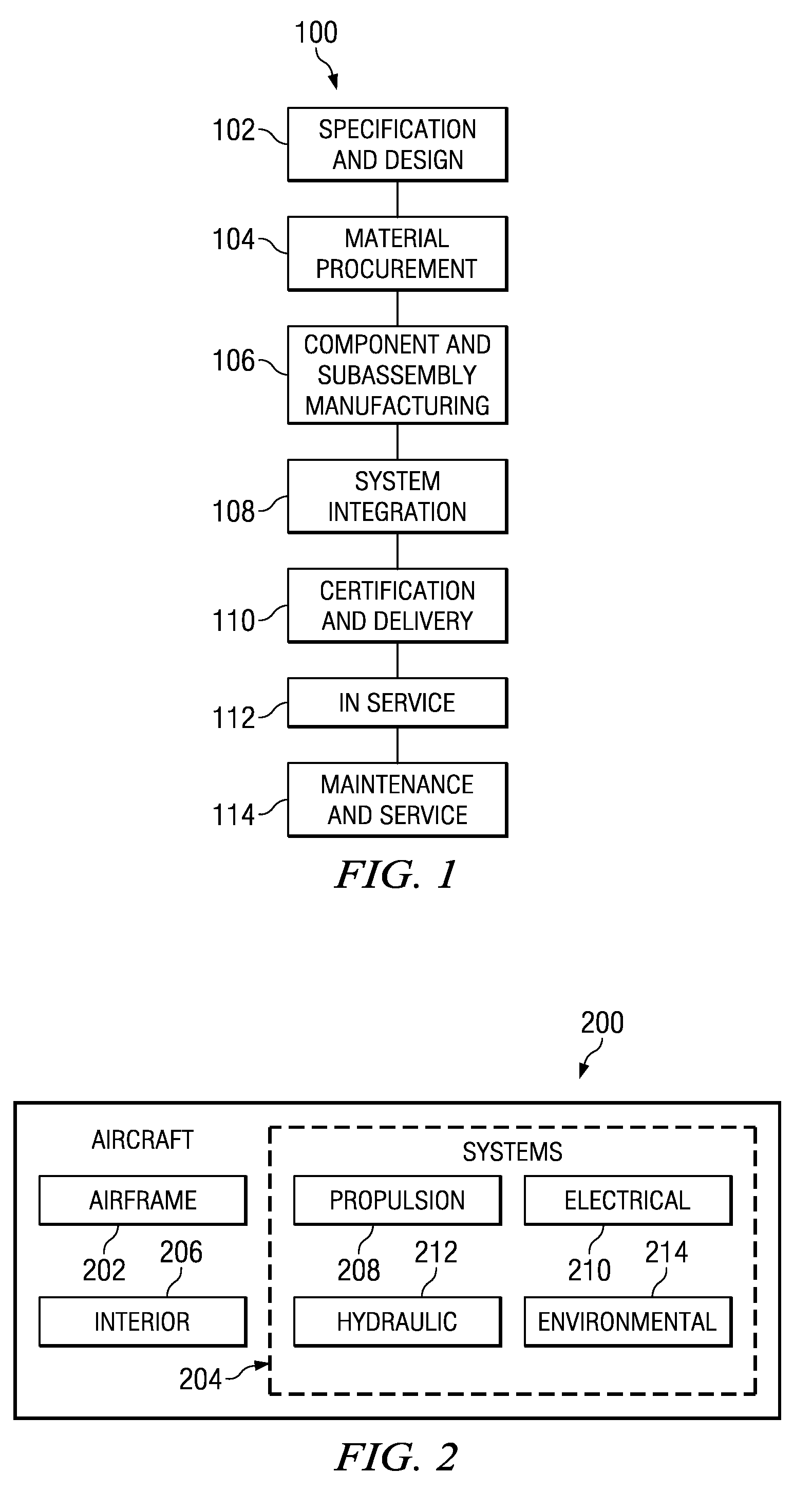
[0031]Referring more particularly to the drawings, embodiments of the disclosure may be described in the context of aircraft manufacturing and service method 100 as shown in FIG. 1 and aircraft 200 as shown in FIG. 2. Turning first to FIG. 1, a diagram illustrating an aircraft manufacturing and service method is depicted in accordance with an advantageous embodiment. During pre-production, exemplary aircraft manufacturing and service method 100 may include specification and design 102 of aircraft 200 in FIG. 2 and material procurement 104.

[0032]During production, component and subassembly manufacturing 106 and system integration 108 of aircraft 200 in FIG. 2 takes place. Thereafter, aircraft 200 in FIG. 2 may go through certification and delivery 110 in order to be placed in service 112. While in service by a customer, aircraft 200 in FIG. 2 is scheduled for routine maintenance and service 114, which may include modification, reconfiguration, refurbishment, and other maintenance or ...


PUM

PropertyMeasurementUnit
Pressureaaaaaaaaaa

Abstract

A measurement targeting apparatus comprises a target body, a vessel with a channel, a fluid located within the channel in the vessel, and a pressurization system. The target body is selected from one of a photogrammetry target, a theodolite target, a construction ball, a touch probe target, a coordinating measurement machine probe target, a laser tracker target, and a laser projector target. The vessel has a centerline, has a substantially cylindrical portion capable of being received in a hole in a part, and is comprised of a material selected from steel, aluminum, and plastic. The vessel is capable of expanding when the fluid within the channel in the vessel is pressurized. The pressurization system is capable of pressurizing the fluid within the channel to cause the vessel to expand around the centerline.

Description

BACKGROUND INFORMATION[0001]1. Field[0002]The present disclosure relates generally to measurement systems and in particular to a method and apparatus for measuring a part. Still more particularly, the present disclosure relates to a method and apparatus for measuring features on a part.[0003]2. Background[0004]Maintenance, modification, and / or repair of aircraft may be commonly performed. These operations may be performed on commercial, military, and other suitable types of aircraft. During these types of operations, a new part may be created to replace a part that may be worn out and / or obsolete.[0005]Additionally, new parts may be added to existing parts to change the functionality, operation, and / or performance of an aircraft. New parts may be created to mate with existing parts. The features that may be used to mate one part with another part include, for example, without limitation, holes and / or pins.[0006]For example, without limitation, a new part may have a pattern of holes ...

Claims


Application Information

Patent Timeline
IPC IPC(8): G01C11/00G01B21/10B23P17/00
CPCG01B21/042G01C25/00Y10S33/15Y10T29/49
Inventor PIASSE, MICHAEL L.WILSON, JONATHAN B.SCHEVERS, IKE C.
Owner THE BOEING CO
Why Eureka
Try Eureka