
Storage Device, and Data path Failover Method of Internal Network of Storage Controller

Inactive Publication Date: 2010-05-06
HITACHI LTD
View PDF30 Cites 62 Cited by
  • Summary
  • Abstract
  • Description
  • Claims
  • Application Information

AI Technical Summary

Benefits of technology

[0013]The present invention was created to resolve this problem and it is an object thereof to provide a feature enabling the execution of data path failover in relation to a storage device in which the MR-IOV is applied to an internal network (CN) of a storage controller.
[0024]The effects that can be obtained with representative embodiments of the invention disclosed in the present application will be described below in a simple manner. The representative embodiment of the present invention relates to a storage device in which the MR-IOV is applied to an internal network of a storage controller and a data path failover can be executed even when a failure occurs in a data path from the RP to the EPD in the storage controller (internal network). Therefore, high reliability can be ensured because the failover can be performed to other data paths.

Problems solved by technology

The resultant problem is that no data path failover can be executed in a storage device in which the MR-IOV is applied to an internal network (CN) of a storage controller.

Method used


Image

  • Storage Device, and Data path Failover Method of Internal Network of Storage Controller
  • Storage Device, and Data path Failover Method of Internal Network of Storage Controller
  • Storage Device, and Data path Failover Method of Internal Network of Storage Controller

Examples


embodiment 1

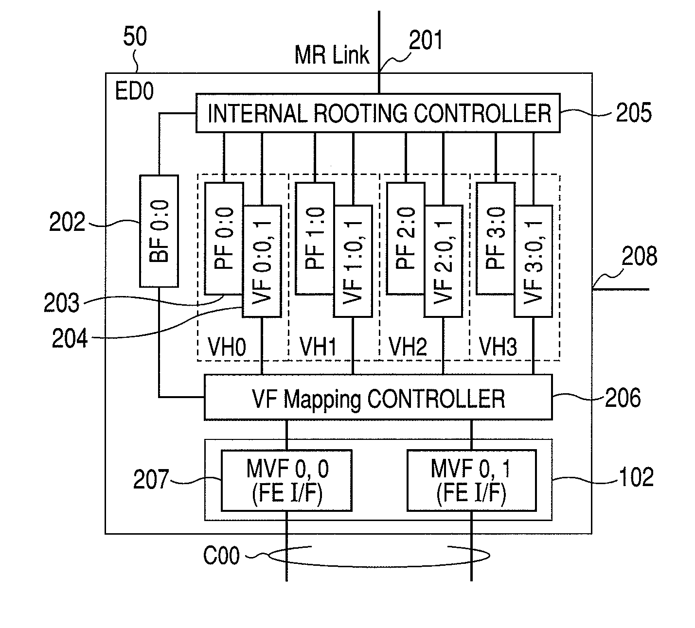
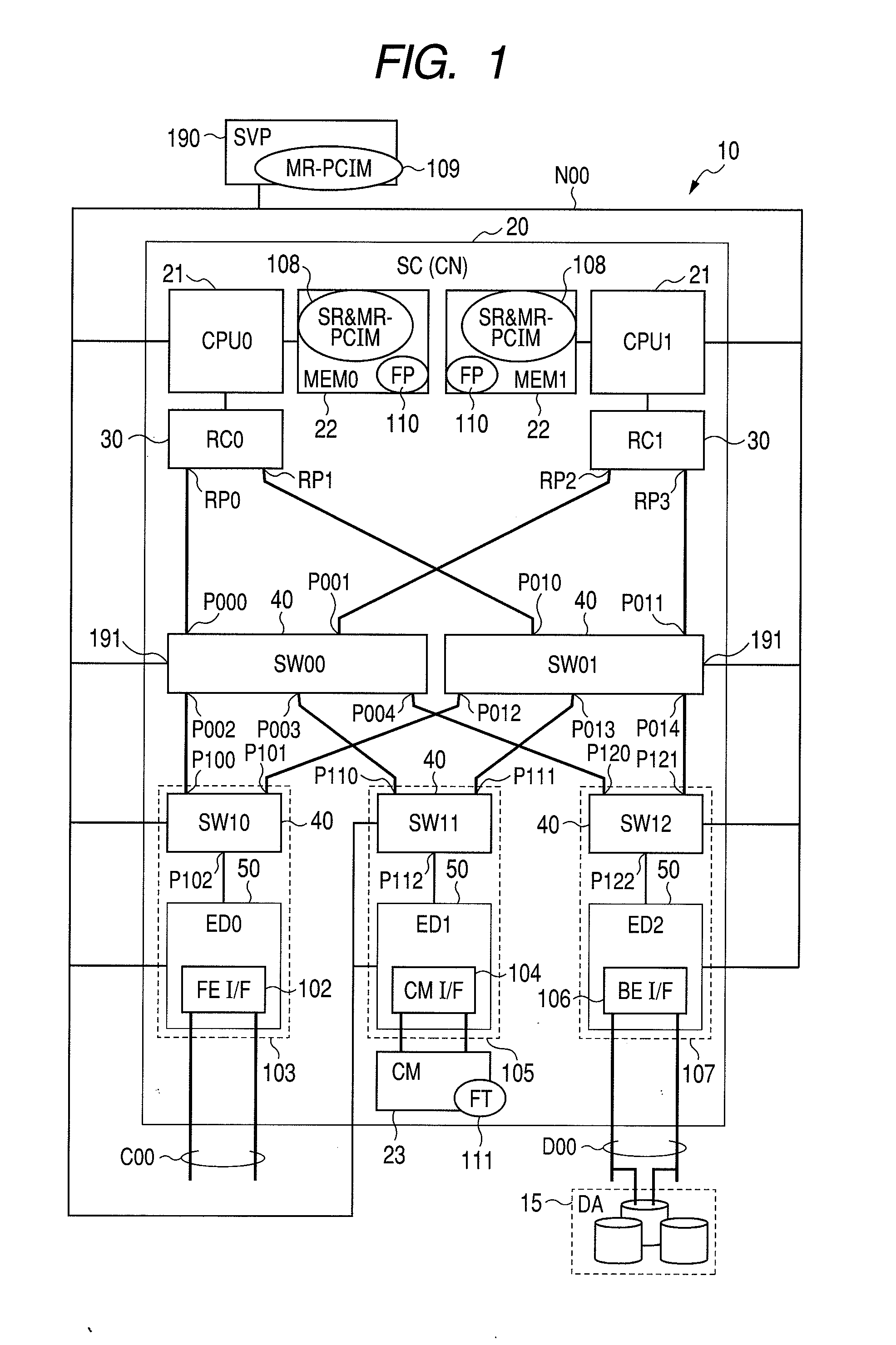
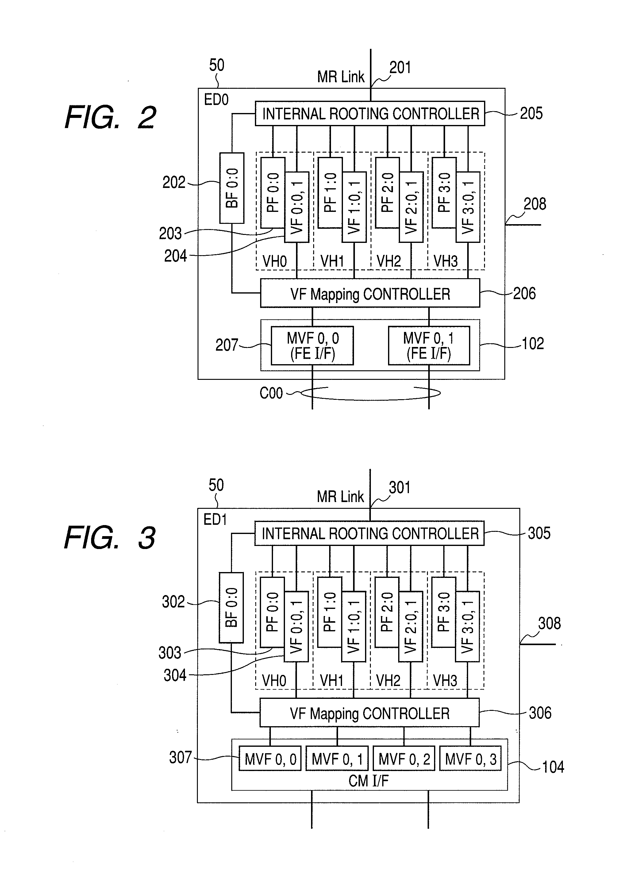
[0055]A storage device (in other words, a storage system) of Embodiment 1 of the present invention will be described below with reference to FIGS. 1-20. Summarizing Embodiment 1, as shown in FIGS. 16, 17, and the like, on the basis of the configuration shown in FIGS. 1, 2, and the like, in an internal network of a storage controller, the failover operation from a normal data path (failure state) to an alternative data path is realized by changing a root port of an access source (for example, RP0→RP1) and also changing the mapping (VF mapping) of a virtual function (VF) of an endpoint device to a mission virtual function (MVF) as a control of VF migration (for example, “VF 0:0, 1”→“MVF 0:0”→“VF 1:0, 1”—“MVF 0:0” of the ED0).

[0056]FIG. 1 is a block diagram of a storage device 10, which is an embodiment of the present invention. The storage device 10 is provided with a storage controller (SC) 20 and a disk array (DA) 15. The DA 15 is configured by a plurality of memory devices such as ...

embodiment 2

[0166]Embodiment 2 will be described below with reference to FIG. 21 and figures with larger numbers. The configuration of Embodiment 2 is obtained by adding a function (VF state transition means) to the configuration of Embodiment 1.

[0167]The alternative means (VF state transition means) for the VF state transition performed with the SR-PCIM will be explained below. The MR-PCIM executes the VF migration, but part of VF state transition, which is necessary for the VF migration, is executed by the SR-PCIM. However, when a failure occurs in a data path, communication between the SR-PCIM and VF appears to be difficult. As a result, in Embodiment 2, VF state transition means that causes a state transition of VF is provided instead of the SR-PCIM.

[0168]FIG. 21 shows a block configuration of an EPD 51 (for example, ED0) that, instead of the SR-PCIM, can cause the state transition of VFs. The EPD 51 is obtained by adding one BF 2102 (“BF 0:1”) with a function number of 1 to the configurati...


PUM


Abstract

A storage device in which the MR-IOV is applied to an internal network of a storage controller. Data path failover can be executed in the storage device. The internal network of the storage controller is configured to enable the access of a virtual function (VF) “VF 0:0, 1” of each endpoint device (ED0-ED2) from a root port RP0. Likewise, “VF 1:0, 1” of each endpoint device can be accessed from a root port RP1. In a first data path from the RP0 to ED0 in a normal state, “VF 0:0, 1” and “MVF 0, 0” are connected by VF mapping. When a failure occurs on the first data path, the MR-PCIM executes the VF migration, whereby in the second data path from the RP1 to ED0,“VF 1:0, 1” and “MVF 0, 0” are connected by VF mapping. As a result, failover to the second data path is realized.

Description

CROSS REFERENCES TO RELATED APPLICATIONS[0001]This application relates to and claims priority from Japanese Patent Application No. 2008-279101, filed on Oct. 30, 2008, the entire disclosure of which is incorporated herein by reference.BACKGROUND OF THE INVENTION[0002]1. Field of the Invention[0003]The present invention relates to a storage device (also referred to as a disk array device), and more particularly to failover technology of data path of an internal network of a storage controller.[0004]2. Description of the Related Art[0005]A storage device is typically provided with a storage controller (also referred to simply as a controller) and a random-accessible nonvolatile medium. The medium is, for example, a disk array including a large number of hard disk drives (HDD). The storage controller has a front-end interface (abbreviated as FEI / F) for connecting a host device (host system and the like), a back-end interface (abbreviated as BEI / F) for connecting a disk array, and a cac...

Claims


Application Information

Patent Timeline
IPC IPC(8): G06F11/20G06F12/10
CPCG06F11/201
Inventor TANAKA, KATSUYASHIMADA, KENTARO
Owner HITACHI LTD
Learn More