Boot shape maintaining body

Inactive Publication Date: 2010-05-13
INED BUSINESS FASHION PLANNING
View PDF7 Cites 3 Cited by
  • Summary
  • Abstract
  • Description
  • Claims
  • Application Information

AI Technical Summary

Benefits of technology

[0012]Since the invention with the above-described configuration ensures a fixed shape, the shaft part does not bend but stands still, making it possible to keep the upright shape of the boot keeper. With the boot k

Problems solved by technology

If the boots are left in this state for a long time, a crease is formed at the bent part of the shaft part, and, further, shape off-set may

Method used


Image

  • Boot shape maintaining body
  • Boot shape maintaining body
  • Boot shape maintaining body

Examples


first embodiment

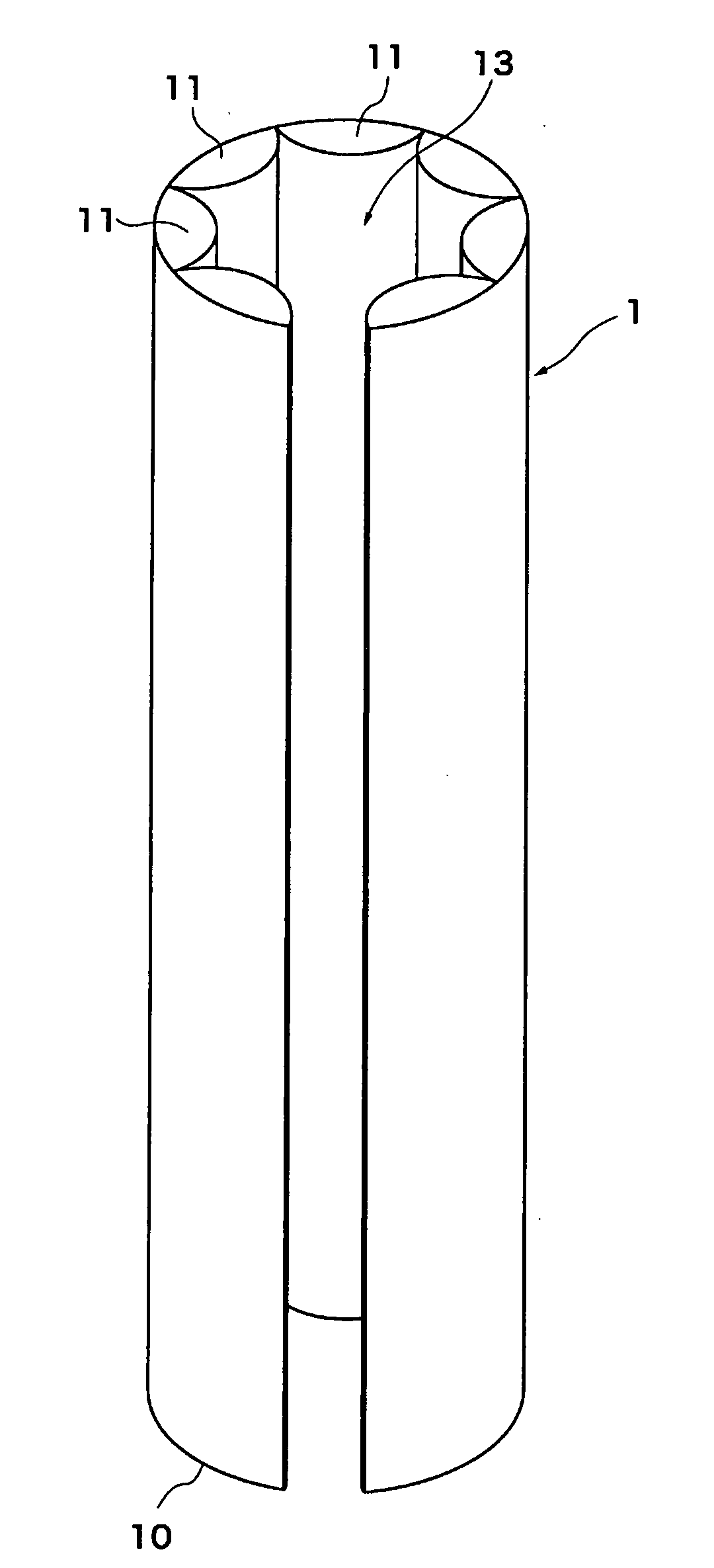
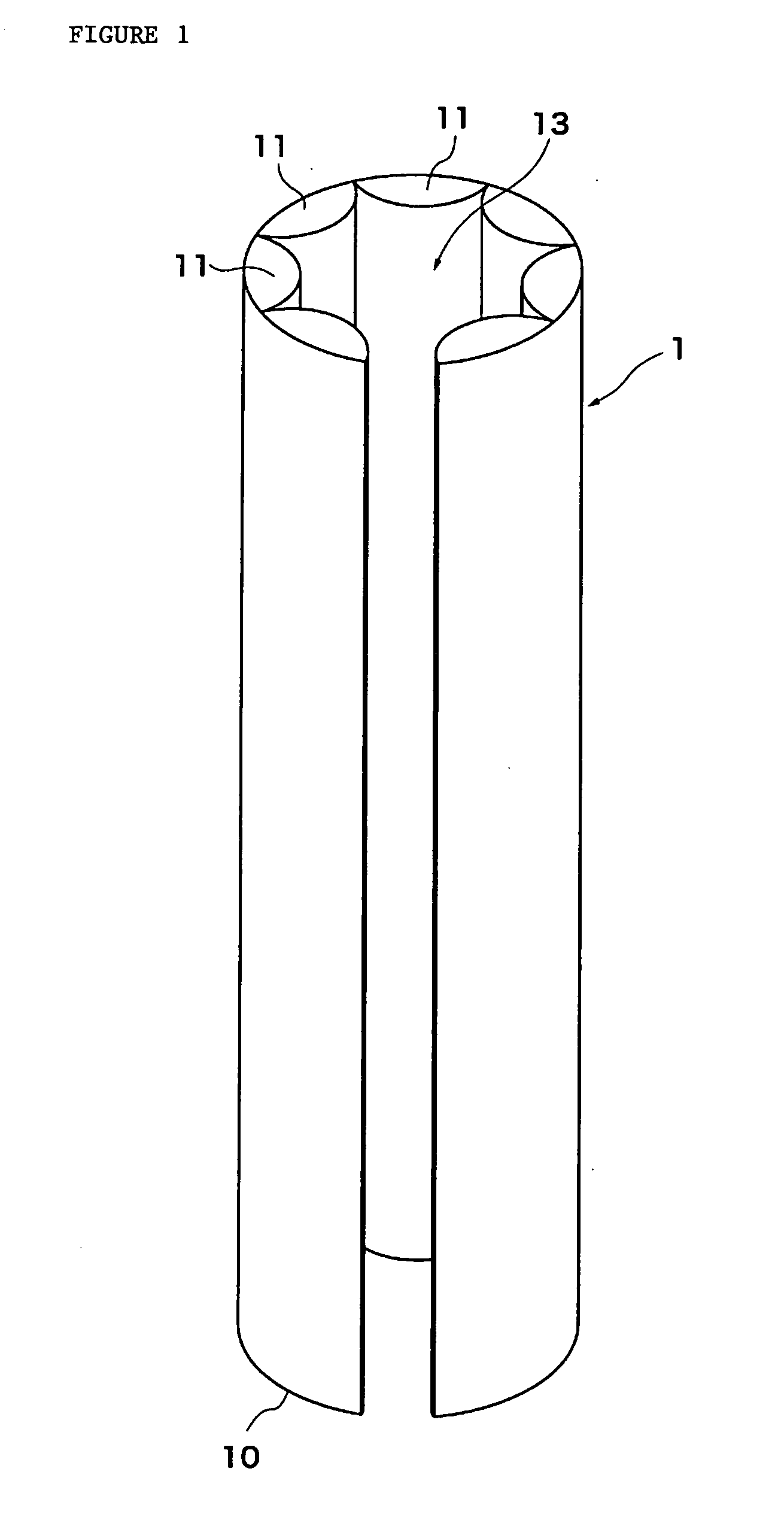
[0023]FIG. 1 shows a perspective view of a boot shape keeper 1 according to a first embodiment to which the invention is applied. This boot shape keeper 1 is formed mainly by rolling a plastic sheet 10 into a coupled cylindrical shape.

[0024]The plastic sheet 10 is a thermoplastic resin sheet, such as non-permeable polyethylene. The thermoplastic resin may be adequately selected from polypropylene, polyethylene terephthalate, nylon, vinyl chloride, polycarbonate, etc. in addition to polyethylene.

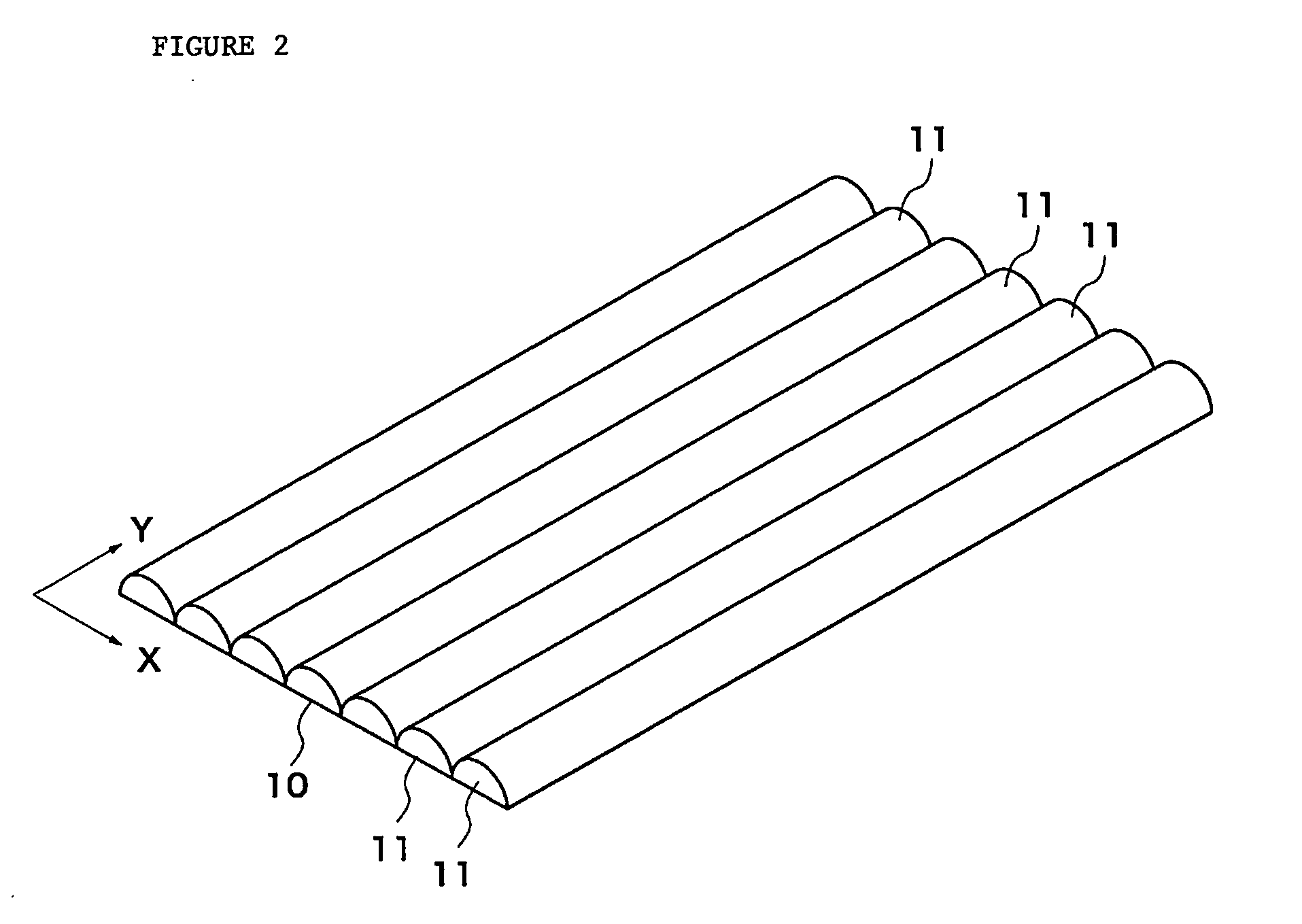
[0025]The plastic sheet 10 has strip air chambers 11 elongated in an up-down direction y and arranged in columns in a widthwise direction x as shown in FIG. 2. A gas is sealed in the air chambers 11 beforehand. The air chambers 11 are formed by placing two rectangular sheets constituting the plastic sheet 10 one on the other and press-bonding the rectangular sheets in the up-down direction, which is not restrictive, and may be realized by any well-known method. In the example of FIG. 2, the a...

second embodiment

[0035]FIG. 5A shows a perspective view of a boot shape keeper 3 according to a second embodiment to which the invention is applied. This boot shape keeper 3 has a body part 30 formed by rolling a plastic sheet with a gas enclosed therein beforehand into a cylindrical shape, and at least one projecting part 32 projecting downward from the lower end of the body part 30. A through hole 31 is formed in the cylindrically formed body part 30. Although the following description will be given of a case where two projecting parts 32 are formed, which is not restrictive, the projecting parts 32 may be formed in any quantity, any volume and any shape.

[0036]The plastic sheet is a thermoplastic resin sheet, such as non-permeable polyethylene. The thermoplastic resin may be adequately selected from polypropylene, polyethylene terephthalate, nylon, vinyl chloride, polycarbonate, etc. in addition to polyethylene.

[0037]The body part 30 can maintain the fixed shape with the air enclosed therein. The ...

third embodiment

[0048]FIGS. 8A and 8B show perspective views of a boot shape keeper 4 according to a third embodiment to which the invention is applied. This boot shape keeper 4 has a body part 40 formed by rolling a plastic sheet with a gas enclosed therein beforehand into a cylindrical shape, and a through hole 42b provided in the lower portion of the side wall of the body part 40, or a groove portion 42a formed in the lower end of the side wall of the body part 40. The groove portion 42a and through hole 42b may have any shape or may be formed in any quantity. The through hole 42b is connected to the through hole 41 in the cylindrical body part 40. Although the location at which the through hole 42b is formed is adjusted beforehand in connection with at least the position of the insole part 23 of the boot 2, it is desirable that the through hole 42b should be formed at any position at least at the lower half. The body part 40 can maintain the fixed shape with the air enclosed therein.

[0049]At th...


PUM


Abstract

Disclosed is a boot shape keeper capable of holding a boot in a fixed shape, removing malodor from the insole of the boot by allowing the insole of the boot to be opened to outside air while the boot is held. The boot shape keeper 1, which is inserted into a shaft part 21 of a boot to keep a shape of the shaft part 21 of a boot, includes a cylindrical body part 30 made by forming a plastic sheet 10 having a gas pre-encapsulated into a cylindrical shape, and a through hole 42b provided at a lower portion of a side wall surface of the body part 30, or a groove portion formed at a lower end of the side wall of the body part 30, wherein the body part 30 has a fixed shape provided by the encapsulated gas.

Description

BACKGROUND OF THE INVENTION[0001]1. Field of the Invention[0002]The present invention relates to a boot shape keeper for holding boots in a fixed shape.[0003]2. Description of the Related Art[0004]With long boots or the like put off and left at a main entrance or the like, the shaft part of the boot bends easily. If the boots are left in this state for a long time, a crease is formed at the bent part of the shaft part, and, further, shape off-set may occur. It is therefore necessary to maintain boots in such a way that the shaft part is not bent when the boots are not used for a long time.[0005]In the past, in order to prevent such bending at the shaft part of a boot, a boot keeper is proposed (for example, refer to Japanese Patent Application Laid-Open No. 2005-6915 (Patent Document 1)). This boot keeper fits in the shaft part of a boot to hold the shape of the shaft part, and has a crease-smoothing member for smoothing a crease formed near the ankle joint of the shaft part. Furthe...

Claims


Application Information

Patent Timeline
IPC IPC(8): A43D3/00
CPCA43D3/1416A43B23/02
Inventor KURITA, TAKAFUMIFUKATSU, ATSUSHI
Owner INED BUSINESS FASHION PLANNING
Why Eureka
Try Eureka