
Controller for fuel pump

Inactive Publication Date: 2010-05-13
DENSO CORP
View PDF0 Cites 14 Cited by
  • Summary
  • Abstract
  • Description
  • Claims
  • Application Information

AI Technical Summary

Benefits of technology

[0009]The present invention is made in view of the above matters, and it is an object of the present invention to provide a controller for a fuel pump which can restrict a usual discharge quantity and can improve a fuel economy.
[0010]According to the present invention, a controller for a fuel pump, which pumps up a fuel in a fuel tank by the fuel pump, filtrates the fuel by a fuel filter and supplies the fuel to an internal combustion engine. The controller includes a filter evaluating means for evaluating a pressure loss of the fuel filter and a control means for controlling a discharge quantity of the fuel pump by controlling a rotational speed of the fuel pump. The control means corrects the rotational speed of the fuel pump in accordance with the pressure loss of the fuel filter evaluated by the filter evaluating means so as to correct the discharge quantity of the fuel pump in accordance with the pressure loss. Thereby, the target discharge quantity and the target rotational speed of the fuel pump are defined in accordance with the actual pressure loss of the fuel filter. Thus, the normal discharge amount of the fuel pump can be reduced, compared with the case that the fuel pump excessively discharges the fuel by the target discharge quantity and at the target rotational speed for the end of life time of the fuel pump. The electricity for the fuel pump is saved and the fuel economy is improved.
[0011]According to another aspect of the present invention, the controller for the fuel pump is provided with a pump evaluation means for evaluating a deterioration degree of the fuel pump. The rotational speed of the fuel pump is corrected in accordance with a deterioration degree and the discharge quantity of the fuel pump is also corrected in accordance with the deterioration degree of the fuel pump. Thereby, the target discharge quantity and the target rotational speed of the fuel pump are defined in accordance with the actual deterioration degree of the fuel pump. Thus, the normal discharge amount of the fuel pump can be reduced, compared with the case that the fuel pump excessively discharges the fuel by the target discharge quantity and at the target rotational speed for the end of life time of the fuel pump. The electricity for the fuel pump is saved and the fuel economy is improved.

Problems solved by technology

Thus, usually, the fuel pump continues to discharge the fuel more than necessary, which wastes an excessive electricity of the fuel pump and deteriorates fuel economy.
However, it is unavoidable that a characteristic of discharge quantity relative to the rotational speed of the fuel pump largely varies with age.
For example, since the fuel discharged from the fuel pump is filtered by a fuel filter, a pressure loss of the fuel filter is a factor which decreases the discharge quantity of the fuel pump.
As a using period of the fuel filter becomes longer, the fuel filter is gradually clogged and the pressure loss of the fuel filter becomes gradually large.
Thus, it is unavoidable that the discharge quantity (fuel quantity supplied to the fuel injector through the fuel filter) is gradually decreased with an increase in pressure loss even if the rotational speed of the fuel pump is unchanged.
Besides, as a using period of the fuel pump becomes longer, a sliding portion of each part is gradually worn away and a fuel leakage in the fuel pump is gradually increased, so that a pump efficiency is deteriorated.
Thus, it is unavoidable that the discharge quantity is gradually decreased with a deterioration in pump efficiency even if the rotational speed of the fuel pump is unchanged.
Even though the pressure loss of the fuel filter and the deterioration degree of the fuel pump are normally less than that at the end of lifetime thereof, the fuel pump excessively discharges the fuel by the target discharge quantity and at the target rotational speed for the end of lifetime thereof.
That is, the fuel pump wastes the excessive electricity to deteriorate the fuel economy.

Method used


Image

  • Controller for fuel pump
  • Controller for fuel pump
  • Controller for fuel pump

Examples


first embodiment

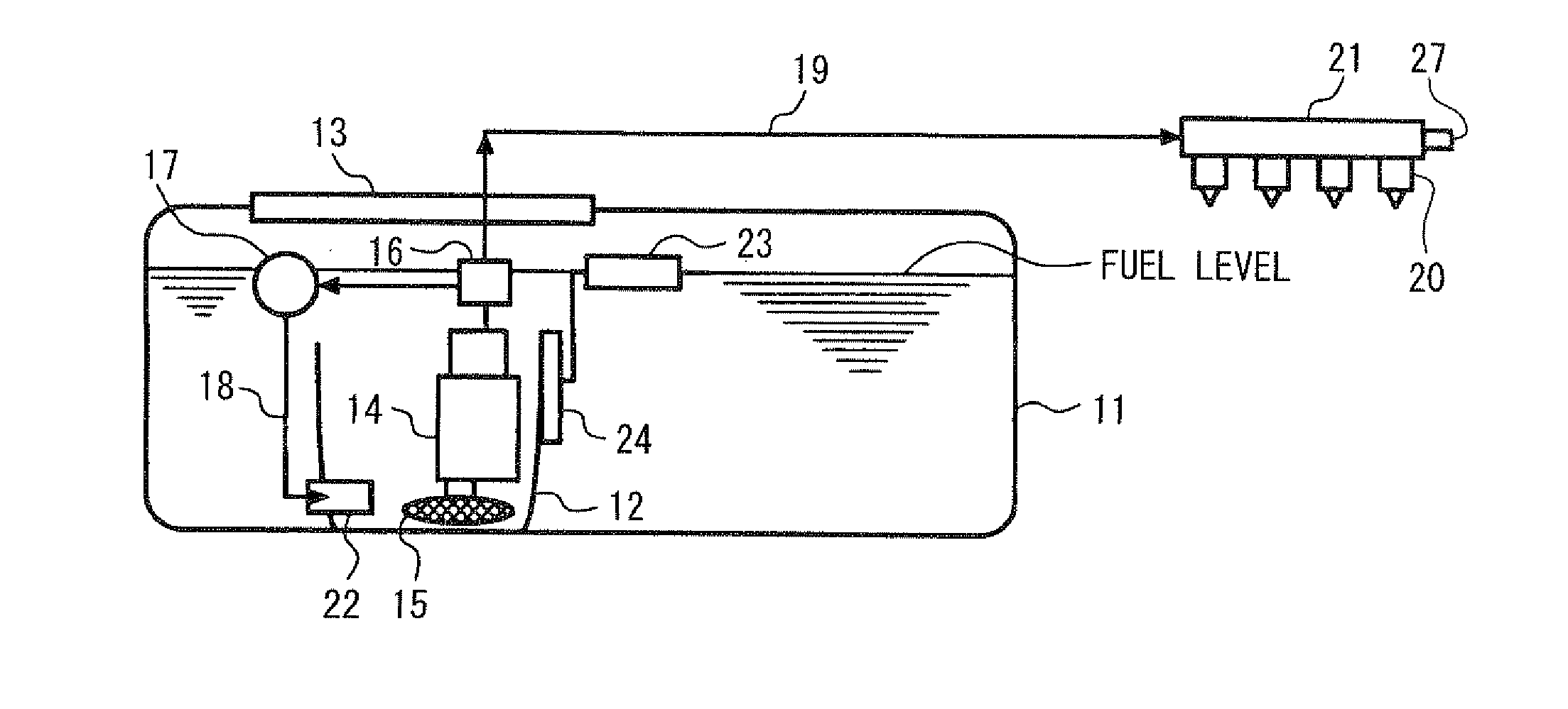
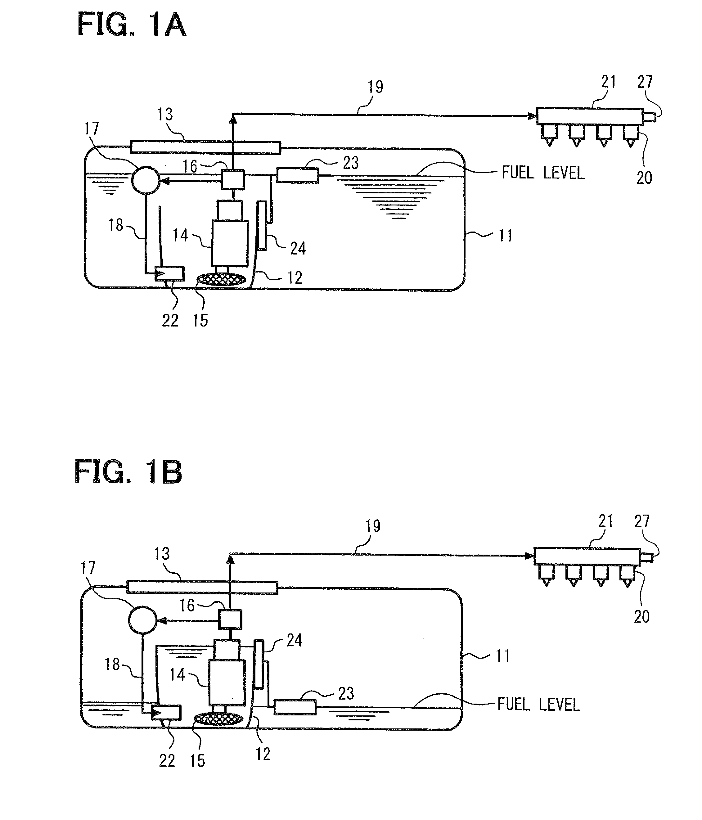
[0024]Referring to FIGS. 1A to 5, a first embodiment will be described hereinafter. First, an entire configuration of a fuel supply apparatus pump is schematically explained based on FIGS. 1A and 1B. A fuel tank 11 accommodates a sub-tank 12. As shown in FIG. 1B, when a remaining fuel quantity in the fuel tank 11 is small, a jet pump 22 gathers the fuel into the sub-tank 12. A flange 13 supporting the sub-tank 12 through an elastic member such as a spring is fixed on the fuel tank 11. As shown in FIG. 1A, when a fuel level in the fuel tank 11 is higher than an upper opening of the sub-tank 12, the fuel in the fuel tank 11 is introduced into the sub-tank 12 through the upper opening thereof so that the sub-tank 12 is filled with the fuel.

[0025]A fuel pump 14 is provided in the sub-tank 12, A suction filter 15 is provided at an suction port of the fuel pump 14. A fuel filter 16 and a pressure regulator 17 are provided at a discharge port of the fuel pump 14. The fuel filter 16 filtrat...

second embodiment

[0048]Referring to FIGS. 6 and 7, a second embodiment of the present invention will be described hereinafter. However, an explanation is omitted or simplified about the substantially same portion as the first embodiment, and only the different portion is mainly explained.

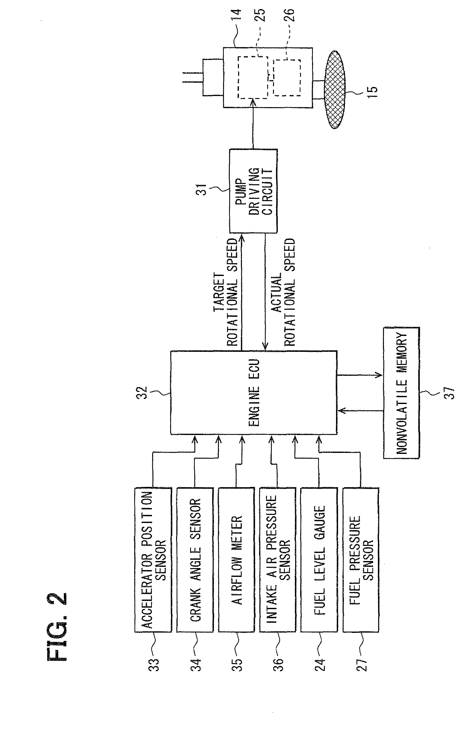
[0049]According to the second embodiment, the engine ECU 32 executes a target rotational speed computing routine shown in FIG. 6 and functions as a pump deterioration evaluating means for evaluating a deterioration degree of the fuel pump 14, The rotational speed of the fuel pump 14 is corrected in accordance with the deterioration degree of the fuel pump 16 and the discharge quantity of the fuel pump 14 is corrected in accordance with the deterioration degree of the fuel pump 16. In order to realize this correction, the engine ECU 32 functions as a target discharge quantity computing means for computing the target discharge quantity by correcting the required fuel quantity with the pump deterioration correction amo...

third embodiment

[0060]Referring to FIG. 8, a third embodiment of the present invention will be described hereinafter. However, an explanation is omitted or simplified about the substantially same portion as the first and the second embodiment, and only the different portion is mainly explained.

[0061]According to the third embodiment, the engine ECU 32 executes a target rotational speed computing routine and functions as a filter pressure loss evaluating means for evaluating the pressure loss of the fuel filter 16 and a pump deterioration degree evaluating means for evaluating the deterioration degree of the fuel pump 14. The rotational speed of the fuel pump 14 is corrected in accordance with the pressure loss of the fuel filter 16 and the deterioration degree of the fuel pump 14, whereby the discharge quantity of the fuel pump 14 is corrected in accordance with the pressure loss of the fuel filter 16 and the deterioration degree of the fuel pump 14.

[0062]The target rotational speed computing routi...


PUM


Abstract

An integrated value of discharge quantity of a fuel pump is used as a parameter evaluating a pressure loss of a fuel filter. A target discharge quantity is obtained by correcting a fuel quantity required by an engine with a filter pressure loss correction amount corresponding to an integrated value of the discharged quantity. A target rotational speed of the fuel pump is computed based on the target discharge quantity, so that the target rotational speed is corrected in accordance with the pressure loss of the fuel filter. Alternatively, the target rotational speed may be corrected in accordance with a deterioration degree of the fuel pump.

Description

CROSS-REFERENCE TO RELATED APPLICATION[0001]This application is based on Japanese Patent Application No. 2008-287104 filed on Nov. 7, 2008, the disclosure of which is incorporated herein by reference.FIELD OF THE INVENTION[0002]The present invention relates to a controller for a fuel pump which pumps up a fuel in a fuel tank and supplies the fuel to an internal combustion engine.BACKGROUND OF THE INVENTION[0003]A conventional fuel supply apparatus is provided with a pressure regulator at an outlet of a fuel pump which pumps up a fuel in a fuel tank. The fuel pump is driven at a constant speed and discharges the fuel in a constant quantity. The pressure regulator adjusts a pressure of fuel discharged from the fuel pump at a constant pressure. The adjusted fuel is supplied to a fuel injector.[0004]In this case, since the fuel pressure is configured to be able to discharge the fuel corresponding to a maximum fuel consumption of the engine, the discharge quantity of the fuel pump is usu...

Claims


Application Information

Patent Timeline
IPC IPC(8): F02M37/04F04B49/00
CPCF02D41/2464F02M37/46F02M37/10F02D41/3082
Inventor FURUHASHI, DAIJINAGATA, KIYOSHINAKABAYASHI, KATSUHIKO
Owner DENSO CORP
Features
  • Generate Ideas
  • Intellectual Property
  • Life Sciences
  • Materials
  • Tech Scout
  • Unparalleled Data Quality
  • Higher Quality Content
  • 60% Fewer Hallucinations
Learn More