
Portable lathe jig

Active Publication Date: 2016-12-06
DE LESSIO JOSEPH
View PDF10 Cites 0 Cited by
  • Summary
  • Abstract
  • Description
  • Claims
  • Application Information

AI Technical Summary

Benefits of technology

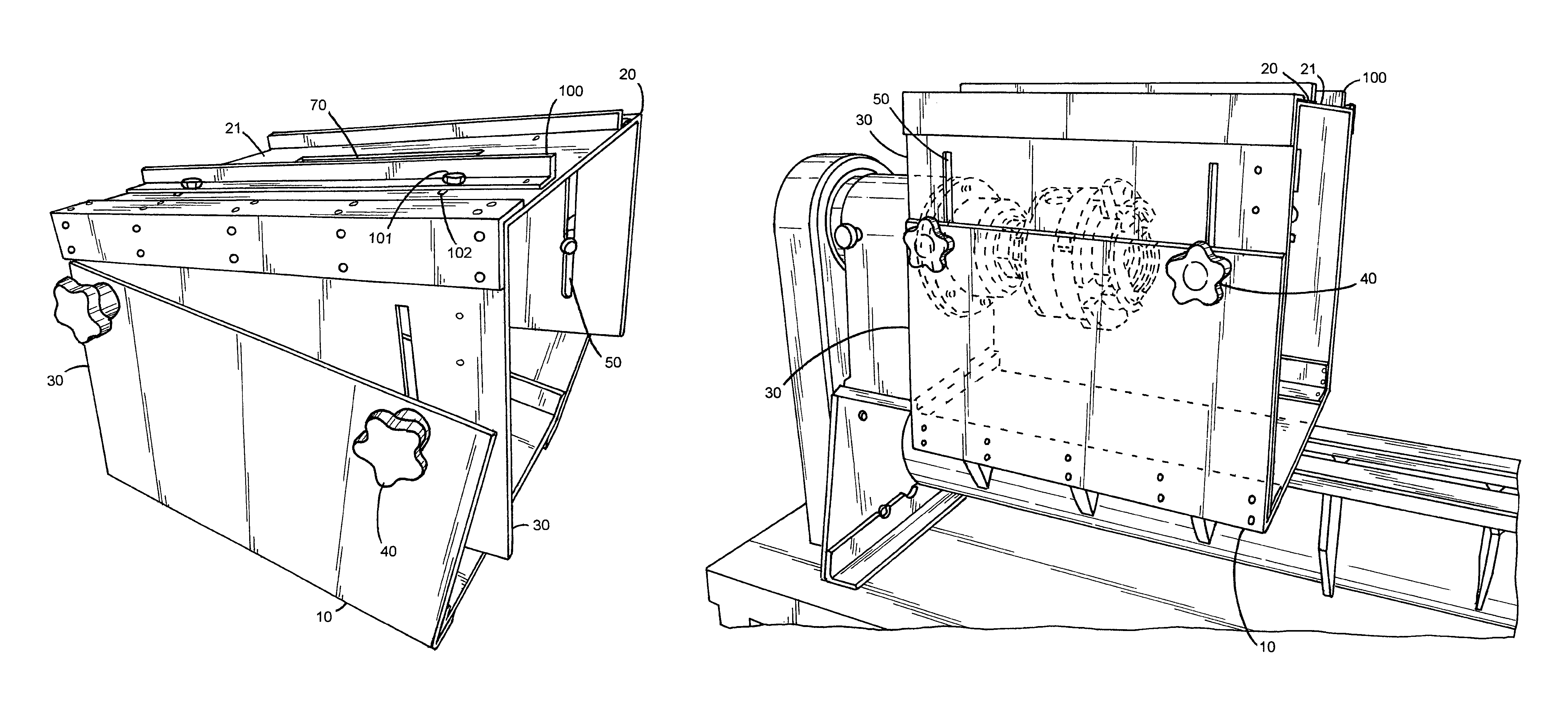
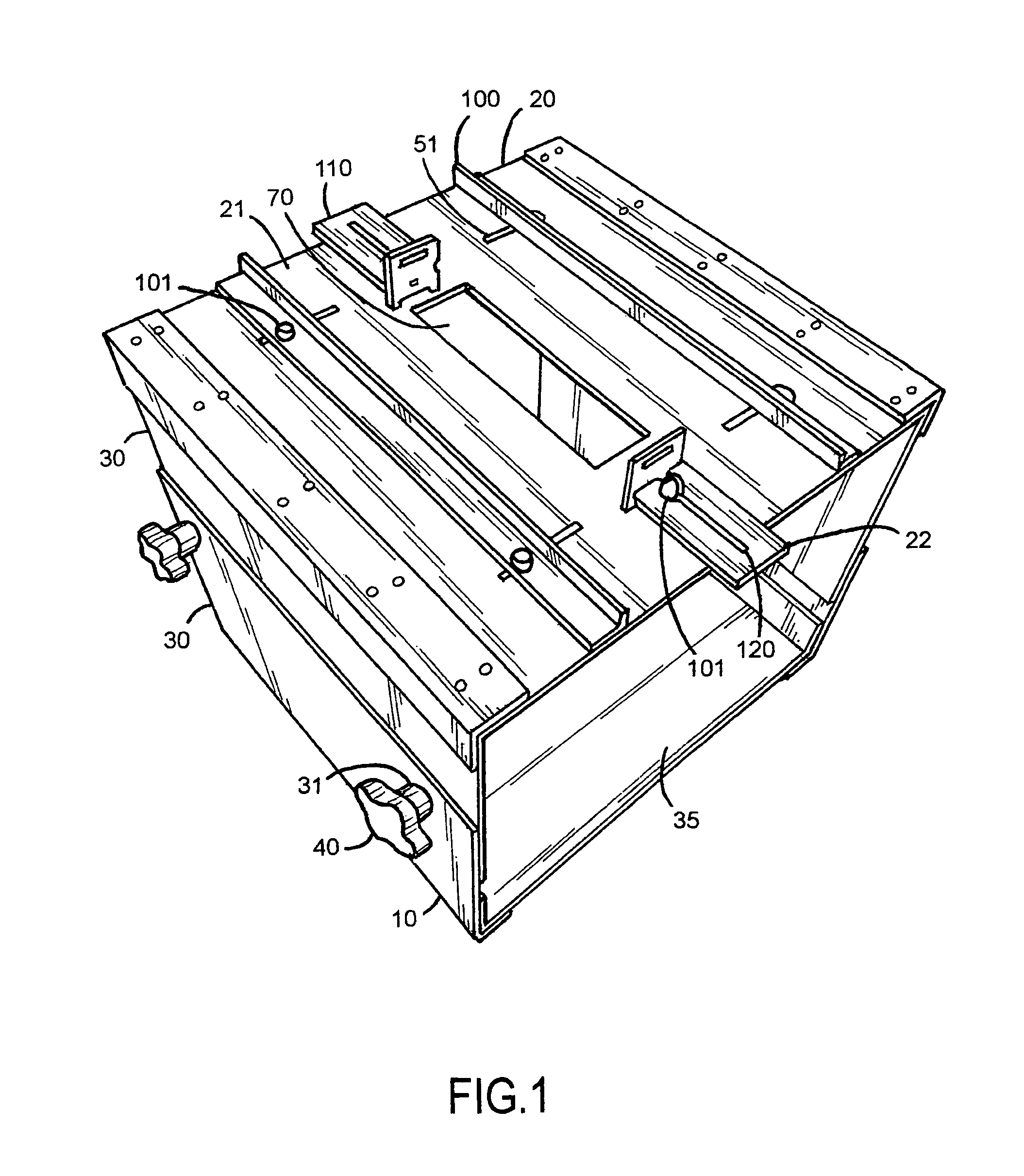
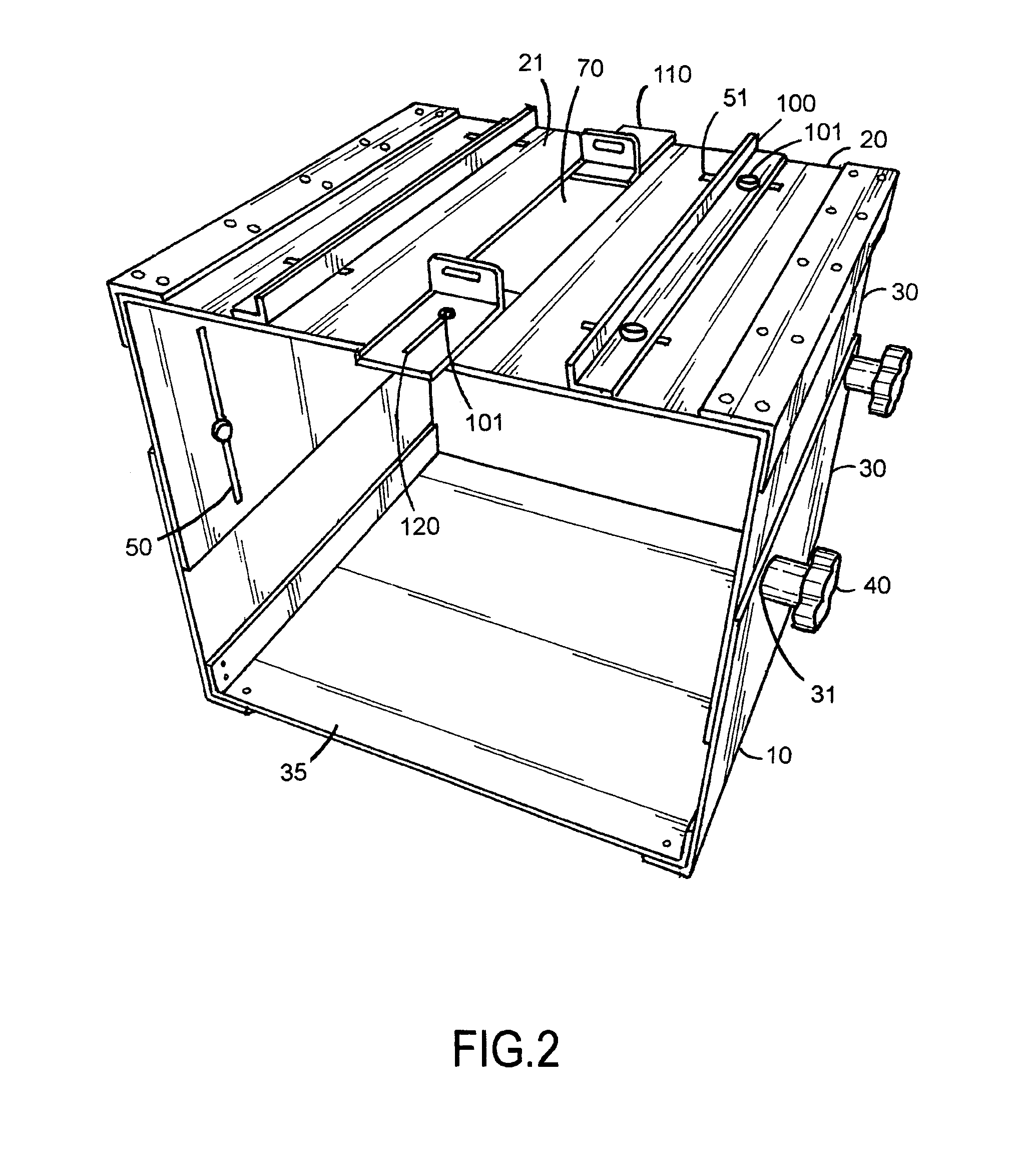
The present invention solves problems in the art by using a hollow frame to adjust needed angles in multiple dimensions. A releasable attachment of the device to the lathe provides versatility and improves economy. The portable lathe jig keeps the operator's hands and body away from the workpiece, resulting in better safety. More precision is achievable for repeatable effects on the workpiece, such as design or functional aspects. The ability to change hand tool bits and / or attachments and keep the same settings for additional effects on the workpiece saves time. The invention also allows for angled and / or curved designs and functional aspects.

Problems solved by technology

Problems in the art are non-precise control of a hand router, for example, wasted time and lack of precision for repeatable details, increasing manufacturing labor and associated costs, and free-hand applied designs which may cause injuries.
One problem versions of this device solve is the ability of using a hand router (or other hand tool) on a workpiece in a precise repeatable pattern for aesthetic beauty and labor time savings for producing multiple copies of a product, like a wooden, plastic or metal bowl, for example, versus a cantilevered tool rest or free-hand of the old art.
No portable lathe jig device and / or system is known to this inventor that addresses these deficiencies in the earlier art in conventional lathe jigs.

Method used


Image

  • Portable lathe jig
  • Portable lathe jig
  • Portable lathe jig

Examples


Embodiment Construction

[0035]It is understood that whenever and / or is used in this patent application it means any combination or permutation of all, one, some, a plurality or none of each of the item or list mentioned, which is not intended to be limiting but merely for example and illustration. It is also understood that (s) designates either singular or plural. It is also understood that “or” is an inclusive “or” to include all items in a list and not intended to be limiting and means any combination or permutation of all, one, some, a plurality or none of each of the item or list mentioned. It is also understood that “include(s)” and / or “including” means “including but not limited to” any combination or permutation of all, one, some, a plurality or none of each of the item or list mentioned. It is further understood that the present invention is not limited to the particular methodology, materials, uses and applications described herein, as these may vary. Structures described herein are to be underst...


PUM

PropertyMeasurementUnit
Lengthaaaaaaaaaa
Angleaaaaaaaaaa
Widthaaaaaaaaaa

Abstract

An article of manufacture, a portable lathe jig device for use with a lathe and hand tools, such as router is disclosed, with a top U-shaped unit with fences and stop plates slidably engaged to a bottom U-shaped unit and the units are movable or locked together with knobs with threaded tightening bolts.

Description

COPYRIGHT NOTICE[0001]A portion of the disclosure of this Patent document, including the drawings and Appendices, contain material which is subject to copyright protection. The copyright owner has no objection to the facsimile reproduction by anyone of the Patent document or the Patent disclosure as it appears in the Patent and Trademark Office Patent files or records, but otherwise reserves all copyright rights whatsoever.BACKGROUND OF THE INVENTION[0002]Field of the Invention[0003]Versions and embodiments of the present invention relate generally to lathes and accessory equipment. Particularly, embodiments of the invention relate to lathes jigs for hand tools and uses thereof. Specifically but not intended to be limiting, versions of the invention relate to permanent and portable jigs to allow precise manual router and other hand tool integration with lathes and new, useful and unobvious versions thereof.[0004]Description / Background of the Related Art[0005]The art discussed herein...

Claims


Application Information

Patent Timeline
IPC IPC(8): B23Q3/00B23Q9/00B23B25/00B25H1/00B23Q3/04
CPCB23Q9/0078B23B25/00B25H1/005B25H1/10B25H1/18B23B3/065
Inventor DE LESSIO, JOSEPH
Owner DE LESSIO JOSEPH
Learn More