

Composite Roof Conversion
- Summary
- Abstract
- Description
- Claims
- Application Information
AI Technical Summary
Benefits of technology
Problems solved by technology
Method used
Image

Examples
Embodiment Construction
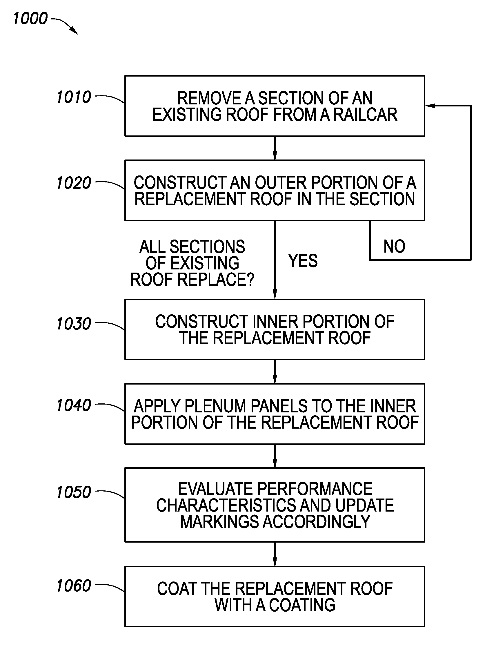
[0017]Particular embodiments disclose a method of converting a composite roof of a railcar. Some or all embodiments disclose removing a composite roof and replacing it with a newly constructed roof, built on the existing railcar. The new roof may provide similar, additional, or different capabilities as the previous, composite roof. For example, in certain embodiments, the railcar may be a refrigerated railcar and the newly constructed roof may provide a similar level of performance with respect to maintaining levels of refrigeration. In particular embodiments, the newly constructed roof may be built on a new railcar.
[0018]The construction process, in various embodiments, may include applying steel beams across the width of the railcar, applying corrugated steel panels to create an exterior portion of the roof, and applying materials, including insulation, interior panels, and plenum panels, to create an interior portion of the roof.
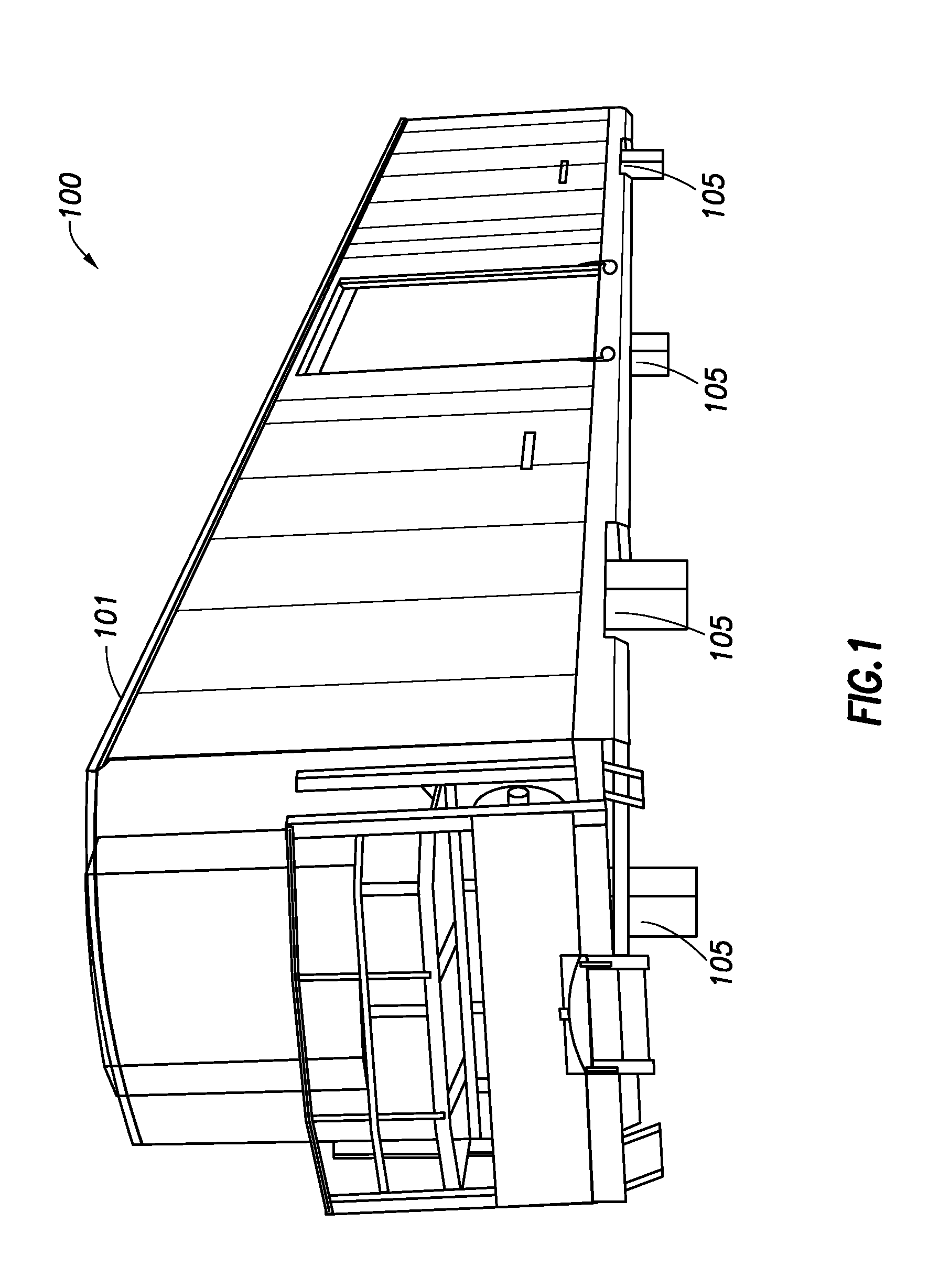
[0019]FIG. 1 illustrates a railcar with a roof in ...
PUM
 Abstract
Description
Claims
Application Information