
Machine tool platform

a technology of a platform and a machining tool, which is applied in the direction of machine supports, manufacturing tools, other domestic articles, etc., can solve the problems of shortening the service life of machine tools, adversely affecting the quality of products, and affecting the quality of mattresses c, so as to reduce the range of vibration of the upper support, improve the effect of vibration reduction, and suppress the vibration

Inactive Publication Date: 2010-05-13
HIWIN MIKROSYST
View PDF7 Cites 3 Cited by
  • Summary
  • Abstract
  • Description
  • Claims
  • Application Information

AI Technical Summary

Benefits of technology

[0009]The primary objective of the present invention is to provide a machine tool platform producing a lateral restraining force which is provided with plural elastic elements and plural stopping members that are oppositely located between a lower base and an upper support, so that if the upper support utilizes the mattresses to horizontally vibrate relative to the lower base, the elastic elements will be compressed by the stopping members to produce a counterforce to act as a lateral restraining force to reduce the range of vibration to offer the effect of vibration reduction.
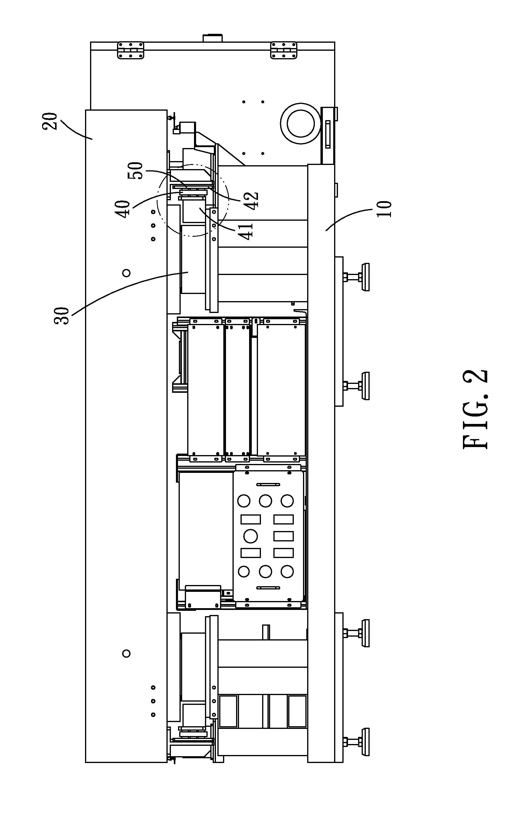
[0011]When a machine tool is disposed on the upper support and actuated to produce vibration, the upper support will be driven to horizontally vibrate relative to the lower base through the mattresses, so that when the respective stopping members are driven to move horizontally, they will be brought into contact to and compress the respective elastic elements, and then the respective elastic elements and stopping members will produce a counterforce, which can act as the lateral restraining force of the upper support to reduce the range of the vibration of the upper support to suppress the vibration.
[0012]In addition, when the respective elastic elements are brought into contact to the respective stopping members, the respective elastic elements will be compressed to avoid the occurrence of vibration due to impact. Furthermore, the respective elastic elements and the respective stopping members are separate from each other if no vibration occurs, so that the vibration of the upper support cannot be transmitted to the lower base, thus further improving the effect of vibration reduction.

Problems solved by technology

Conventionally, machine tools are mostly directly fixed on the ground, and they will cause vibration during machining process, since the ground cannot absorb the vibration of machine tools, the vibration will completely act on the machine tools, thus not only shortening the service life of the parts of the machine tools, but adversely affecting the quality of products.
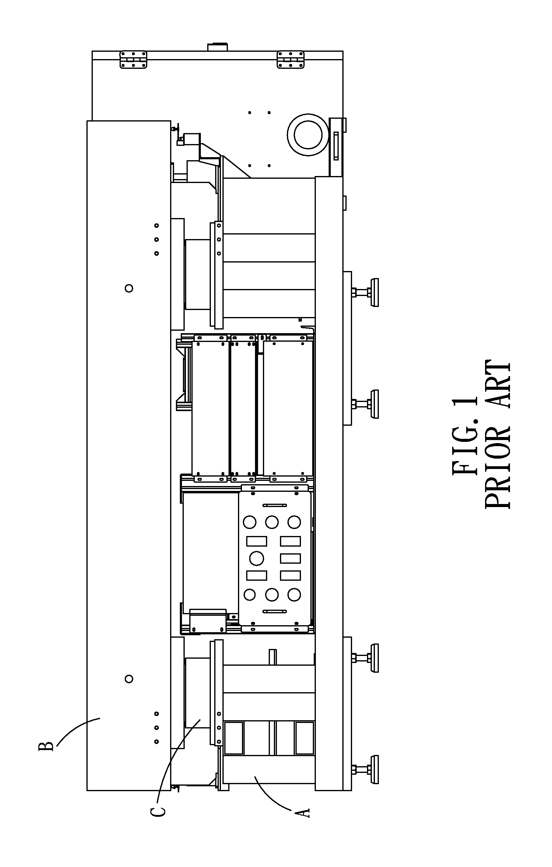
However, if the upper support B is driven by the machine tool to vibrate severely, the mattresses C will be possibly damaged.
The grease damper is difficult to exert a fine vibration-suppressing effect when the upper support B vibrates severely.

Method used


Image

  • Machine tool platform
  • Machine tool platform
  • Machine tool platform

Examples


Embodiment Construction

[0016]The present invention will be clearer from the following description when viewed together with the accompanying drawings, which show, for purpose of illustrations only, the preferred embodiment in accordance with the present invention.

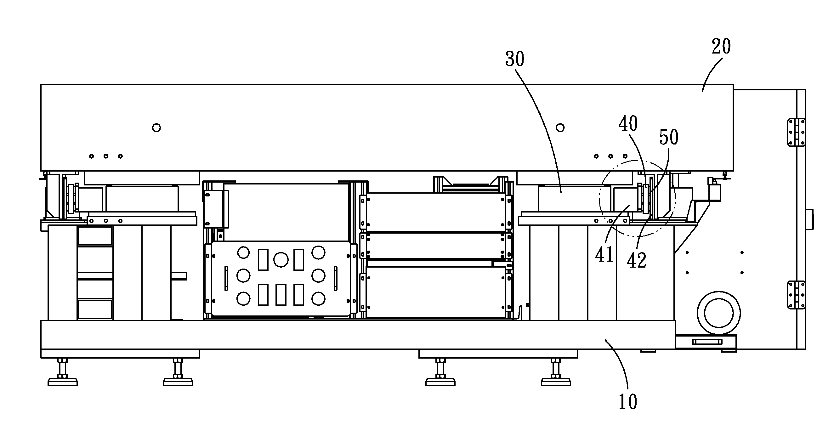
[0017]Referring to FIGS. 2-3, a machine tool platform in accordance with the present invention comprises a lower base 10, an upper support 20, plural elastic elements 40 and plural stopping members 50.

[0018]The upper support 20 is connected to the lower base 10 through plural mattresses 30 in such a manner that the upper support 20 can float above the lower base 10.

[0019]The plural elastic elements 40 are disposed on the lower base by a support frame 41. In the present embodiment, one end of each of the elastic elements 40 is connected to the support frame 41, and the other end of each of the elastic elements 40 is connected to a push plate 42. The elastic elements 40 can be springs, elastic plates or elastomers.

[0020]The plural stopping members ...


PUM


Abstract

A machine tool platform producing a lateral restraining force comprises a lower base and an upper support that are connected to each other through plural mattresses. The lower base is provided with plural elastic elements, the upper support is provided with plural stopping members. By such arrangements, if the upper support horizontally vibrates relative to the lower base, the elastic elements and the stopping members can be used to produce a lateral restraining force to suppress the vibration.

Description

BACKGROUND OF THE INVENTION[0001]1. Field of the Invention[0002]The present invention relates to an accessory for a machining tool, and more particularly to a machine tool platform producing a lateral restraining force.[0003]2. Description of the Prior Art[0004]Conventionally, machine tools are mostly directly fixed on the ground, and they will cause vibration during machining process, since the ground cannot absorb the vibration of machine tools, the vibration will completely act on the machine tools, thus not only shortening the service life of the parts of the machine tools, but adversely affecting the quality of products.[0005]Hence, a conventional machine tool platform was developed on the market, as shown in FIG. 1. This conventional machine tool platform comprises a lower base A and an upper support B. The lower base A is connected to the upper support B through plural mattresses C. When a machine tool (such as gantry crane) is disposed on the upper support B, the vibration c...

Claims


Application Information

Patent Timeline
Patent Type & Authority Applications(United States)
IPC IPC(8): F16M13/00F16M11/00
CPCB23Q11/0032
Inventor LIN, CHIEN-CHENG
Owner HIWIN MIKROSYST
Learn More