Flange assembly, a coupling flange and an assembly method tehreof

a technology of coupling flanges and assembly methods, which is applied in the direction of final product manufacturing, machines/engines, mechanical equipment, etc., can solve the problems of large hoop stress of pipe walls, and limited thickness of flange plates b>1/b>, so as to reduce the force on welding seams, reduce the effect of bending moment of stiffening plates on connecting, and reduce the effect of hoop stress

Active Publication Date: 2010-05-13
INNER MONGOLIA GOLDEN OCEAN NEW ENERGY TECH
View PDF17 Cites 25 Cited by
  • Summary
  • Abstract
  • Description
  • Claims
  • Application Information

AI Technical Summary

Benefits of technology

[0037]1. This invention moves the stiffening plates from the back side of the flange plate to the front side of the flange plate. This is opposite to the prior flanges. And equilibrium contact surfaces are set up one stiffening plates. Therefore after steel pipes are assembled and connected, not only the coupling end surfaces of abutting steel pipes but also the equilibrium contact surfaces of stiffening plates contact each other and get stressed. Therefore, the bending moment created by said equilibrium contact surfaces can basically offset the pulling stress moment imposed on steel pipes walls by bolts through the stiffening plates to achieve a balance. The effect of the bending moment of the stiffening plates on the connecting can be basically eliminated, the hoop stress (or pressure stress) of steel pipes can be reduced, and forces on the welding seams can be greatly reduced. Only shearing force and small pulling force will be imposed on welding seams. This both provides reliable bonding strength and ensures the anti-fatigue performance of welding seams. The tensile rigidity remains unchanged under circulating dynamic load, which totally meets the stress requirements of wind power generator pylons. In addition, since the bending moment effect of the stiffening plates on the connecting welding seams on the steep pipe walls is basically eliminated, it can avoid trend in existing art to increase the height of stiffening plates in order to reduce the hoop stress imposed by stiffening plates on the pipe walls. This invention can reduce the height of stiffening plates.
[0038]2. Since the coupling flange of this invention comprises relatively light and thin flange p...

Problems solved by technology

This coupling flange has the following disadvantages when it is used for fatigue dynamic structures: thickness of Flange Plate 1 is limited.
The diameter of the bolt is so large that is a little hard to meet the requirement on pre-tightening force of a friction-type high-strength bolt.
This bending moment will pass through Stiffening plate 2 and impose a radial pressure on the wall of Steel Pipe 3, and thus lead to a large hoop stress of the pipe wall, which has an adverse effect on the stress of Steel Pipe 3.
Especially when the bolt is under a great pulling force, the flange will split along the upper and lower flange binding surfaces and the bending rigidity cannot be kept unchanged.
Due to the disadvantages of the rigid flange and because wind power generators are subject to the circulating dynamic effects of the rotation of wind wings, pylons are required have sufficient structural strength and bonding strength to withstand such fatigue dynamic load and to withstand the ultimate load brought by maximum wind pressure.
Therefore said rigid flange cannot be used for the pylon connection of wind power genera...

Method used


Image

  • Flange assembly, a coupling flange and an assembly method tehreof
  • Flange assembly, a coupling flange and an assembly method tehreof
  • Flange assembly, a coupling flange and an assembly method tehreof

Examples


embodiment 1

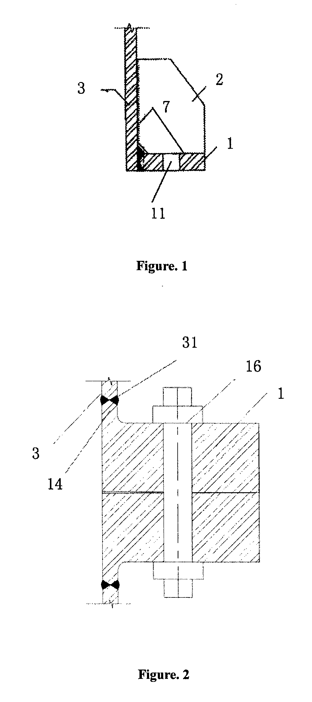
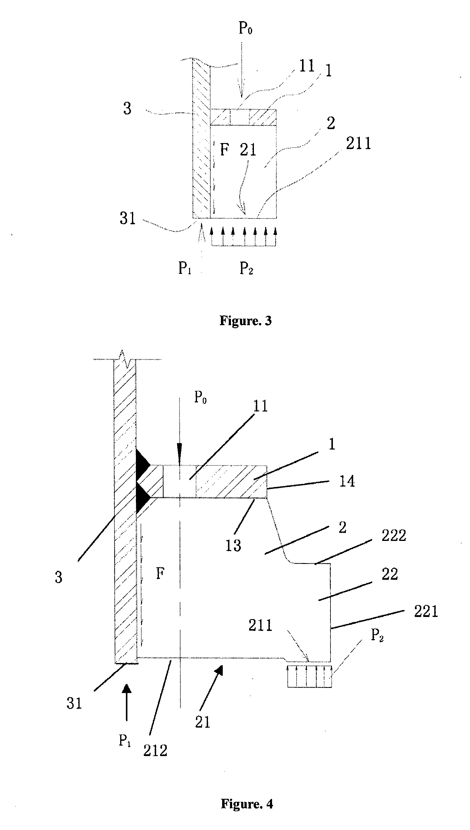
[0052]As shown in FIG. 3, this invention provides a flange assembly comprising Flange Plate 1 and Stiffening Plates 2. In this embodiment, said Flange Plate 1 and Stiffening Plates 2 are located on the inner side of Steel Pipe 3, forming an internal flange assembly. The central axis of the upper and lower Steel Pipe 3 lies on the right of the figure. Several Bolt Holes 11 are set up on Flange Plate 1. Preferably, said Stiffening Plates 2 are evenly distributed along the wall of Steel Pipe 3. Said Bolt Holes 11 are located on the splitting line between the center lines of two neighboring Stiffening Plates 2. As a matter of fact, if there are just a few stiffening plates and each of them is thick enough, Bolt Holes 11 can also go through the main bodies of Stiffening Plates 2. This is optional. Said Bolt Holes 11 just have to connect the two abutting flange assemblies through fastening pieces such as bolts. Stiffening Plates 2 are located on the front side of Flange Plate 1 along the ...

embodiment 2

[0059]See FIG. 3-6. This embodiment basically has the same principles, structure, and effects as Embodiment 1, which will not be repeated here. The difference is: in this embodiment, said Flange Plate 1 and Stiffening Plates 2 are located on the outer side of Steel Pipe 3. Said flange assembly is embodied as an outer flange assembly. This embodiment basically has the same structure as Embodiment 1. Only the inner and outer flanges are different. The central axis of Steel Pipe 3 lies on the right of the figure. Please refer to Embodiment 1 for the details of the structure. They will not be repeated here.

embodiment 3

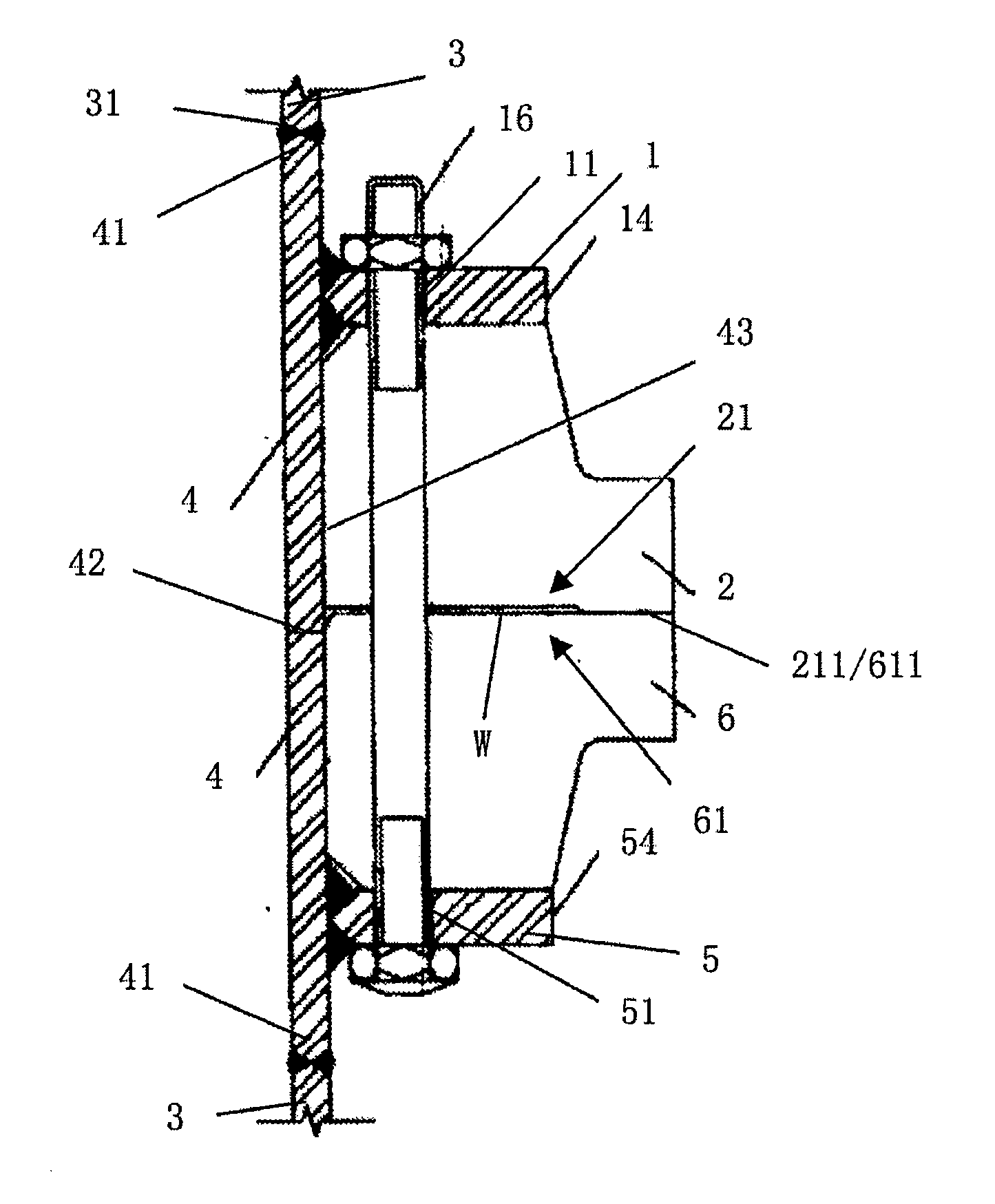
[0060]See FIG. 5. This embodiment basically has the same principles, structures, and effects as Embodiment 1, which will not be repeated here. The difference is that the coupling flange of this embodiment directly comprises an upper assembly and a lower flange assembly fitted together.

[0061]This coupling flange comprises an upper flange assembly and a lower flange assembly. The upper flange assembly comprises an Upper Flange Plate 1 and several Upper Stiffening Plates 2. The lower flange assembly comprises a Lower Flange Plate 5 and several Lower Stiffening Plates 6. In this embodiment, said Upper Flange Plate 1, Lower Flange Plate 5, Upper Stiffening Plates 2, and Lower Stiffening Plates 6 are located on the inner side of Upper and Lower Steel Pipes 3. This coupling flange is an inner coupling flange. The center axis of Upper and Lower Steel Pipes 3 is on the left of the figure.

[0062]Bolt Holes 11 and Bolt Holes 51 are set up respective Upper Flange Plate 1 and Lower Flange Plate 5...


PUM


Abstract

A flange assembly, a coupling flange, and its assembling method thereof are disclosed. Stiffening plates (2) are located on the front side of the flange plate (1). Equilibrium contact surfaces (211) are set up on the front end surfaces of stiffening plates. The pressure stress bending moment created by the equilibrium contact surfaces offsets the pulling stress on the steel pipe wall and reduces the hoop stress of the steel pipe. This provides reliable bonding strength and ensures that the tensile rigidity remains unchanged under circulating dynamic load. This coupling flange is especially suitable for the connection of large-scale steel pipes such as the cylindrical pylons of large-scale wind power generators. The coupling flange can save steel consumption, reduce machining difficulty, and thus greatly reduce the manufacturing and assembling costs.

Description

TECHNICAL FIELD[0001]This invention relates to a pipe coupling flange and its assembling method, especially to a flange assembly, a coupling flange and its assembling method used for large-scale steel pipes such as cylindrical pylons (also known as “tower pipe”) of large-scale wind power generators and other steel pipe structures that have the same stress features.BACKGROUND ART[0002]See FIG. 1. Rigid flanges are generally used in the connection of most steel pipes at present. This rigid flange comprises: Flange Plate 1 welded along the wall of Steel Pipe 3, several Bolt Holes 11 set up on Flange Plate 1, and several Stiffening plates 2 set up on the back of Flange Plate 1. Stiffening plates 2 are welded and fixed to the wall of Steel Pipe 3 and the back of Flange Plate 1 so that Stiffening plates 2 are distributed in the radial direction along Steel Pipe 3. Both pipes are connected by inserting bolts into Bolt Holes 11 on Flange Plate 1. This coupling flange has the following disad...

Claims


Application Information

Patent Timeline
IPC IPC(8): F16L3/00F16L23/026
CPCE04H12/085E04H12/28Y02E10/728F05B2260/301F03D11/04F03D13/20Y02E10/72Y02P70/50
Inventor MA, RENLE
Owner INNER MONGOLIA GOLDEN OCEAN NEW ENERGY TECH
Why Eureka
Try Eureka