Active scanner bow compensator
- Summary
- Abstract
- Description
- Claims
- Application Information
AI Technical Summary
Benefits of technology
Problems solved by technology
Method used
Image

Examples
example 1
[0062]This Example tested the effect of the exemplary compensator as shown in FIGS. 5 and 6 in reducing scanner bow over a 90-μm scan.
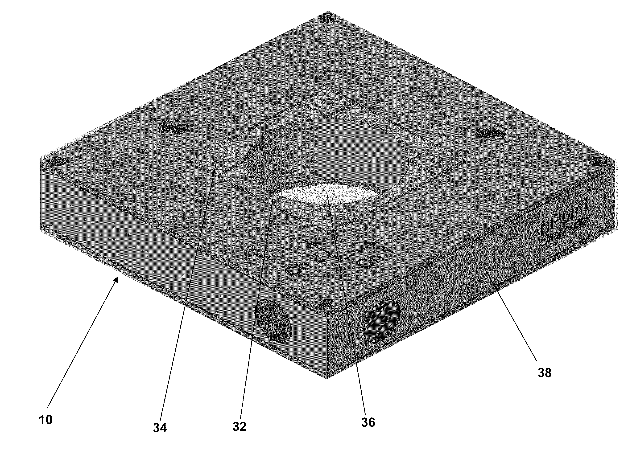
[0063]A sample was mounted in a fixture and attached near a corner of a scanning platform of an XY scanner as shown in FIGS. 5 and 6 using four mounting holes. To obtain an initial reading of scanner bow in the absence of active compensation, 90 μm of the sample was scanned with a Z scanner probe along a single axis of the XY plane, forming a trace, and re-scanned in the opposite direction, forming a retrace. FIG. 7A shows the scanner bow in the sample in the absence of active compensation. The scanner bow was approximately 3 nm over the 90 μm of travel in the XY plane. The same XY scanning procedure was repeated but with active compensation, as shown in FIG. 7B. The scanner bow was reduced to approximately 1 nm over the 90 μm of travel in the XY plane with active compensation.
[0064]This example shows that an active scanner bow compensator can reduce ...
example 2
[0065]This Example tested the effect of the exemplary compensator as shown in FIGS. 5 and 6 in reducing scanner bow over 180-μm scans at various portions of the scanning platform.
[0066]Using a silicon wafer sample, the out-of-plane motion was characterized over a 180-μm scan at the center and at a corner of the scanning platform. The same AFM configuration and methods were used as described in Example 1.
[0067]FIG. 8A shows the out-of-plane motion occurring at the center of the scanning platform in the absence of active compensation. Significant scanner bow was observed with both the scan and re-scan. Additionally, inconsistencies between the scan and re-scan were observed. FIG. 8B shows the out-of-plane motion occurring at the center of the scanning platform with active compensation. Both a reduction in out-of-plan motion and an increase in the consistency between the scan and re-scans were observed with active compensation.
[0068]FIGS. 9A and 9B show the out-of-plane motion occurrin...
example 3
[0070]This Example tested whether a vertical load on the scanning platform affects the compensation properties of the compensator.
[0071]Scanning both X and Y axes of the XY plane was performed with a 200 g load on the scanning platform with active compensation. FIG. 10A shows the out-of-plane motion at the center of the scanning platform with a scan taken along the X axis. FIG. 10B shows the out-of-plane motion also at the center of the scanning platform but with a scan taken along the Y axis. FIGS. 10A and 10B show that even with a 200 g load, the scanner was capable of maintaining scanning consistency and minimal scanner bow when using active compensation. Similar results were obtained when the scanning was performed at the corner of the scanning platform (data not shown).
[0072]This Example shows that the compensator disclosed herein is capable of operating with vertical loads reaching 200 g.
PUM
 Abstract
Description
Claims
Application Information
PatSnap Eureka turns technology decisions into work you can execute. Powered by our Innovation Knowledge Graph, it runs expert workflows across engineering, life sciences, materials and intellectual property. Get your review-ready output in minutes.


