Eureka AIR delivers breakthrough ideas for toughest innovation challenges, trusted by R&D personnel around the world.

Multi Mode Safety Control Module

a safety control module and multi-mode technology, applied in the direction of pedestrian/occupant safety arrangement, special data processing applications, electric devices, etc., can solve the problems of complex installation, inflexible, and inability to adapt to the application of safety systems,

Active Publication Date: 2010-05-13
IROBOT CORP
View PDF98 Cites 46 Cited by
  • Summary
  • Abstract
  • Description
  • Claims
  • Application Information

AI Technical Summary

Benefits of technology

The present patent provides a robotic assembly and a system for controlling the distribution of power within a mobile vehicle. The robotic assembly includes a mobile vehicle with mechanical components and a main power circuit for distributing power to the mechanical components and external modules. The assembly also includes an automation module for controlling and operating the mechanical components and distributing power. The system also includes emergency stop buttons and a safety control module with a mode selector switch for altering the vehicle's mode of operation. The power control system includes a safety control module, a mode switch circuit, and an emergency stop switch. The technical effects of the present patent include improved safety and control over the distribution of power within a mobile vehicle.

Problems solved by technology

Such a configuration can be disadvantageous because it provides no alternative to removing power from the entirety of the system.
Additionally, safety systems that integrate the circuits and mechanical systems necessary to implement an emergency stop safety system can be application specific, not versatile, and require costly and often complicated installation.
It may be inappropriate to design an autonomous vehicle that responds to an emergency event by removing power from all components within the autonomous vehicle.
Such a design would fail to address the need for an autonomous vehicle to retain a level of autonomy despite encountering an emergency event that causes a power loss.

Method used


Image

  • Multi Mode Safety Control Module
  • Multi Mode Safety Control Module
  • Multi Mode Safety Control Module

Examples


Embodiment Construction

[0019]Reference will now be made in detail to the present exemplary embodiments of the present teachings, examples of which are illustrated in the accompanying drawings.

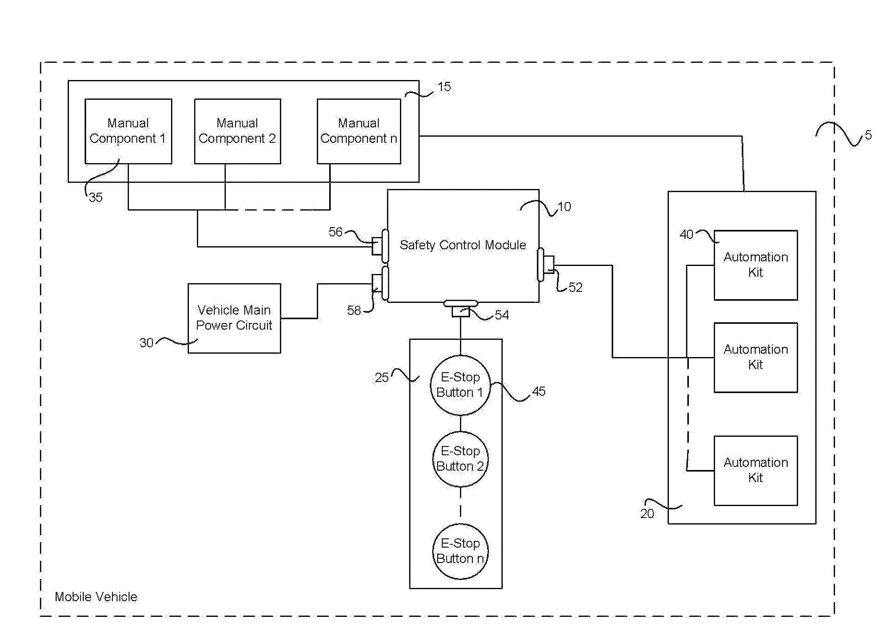
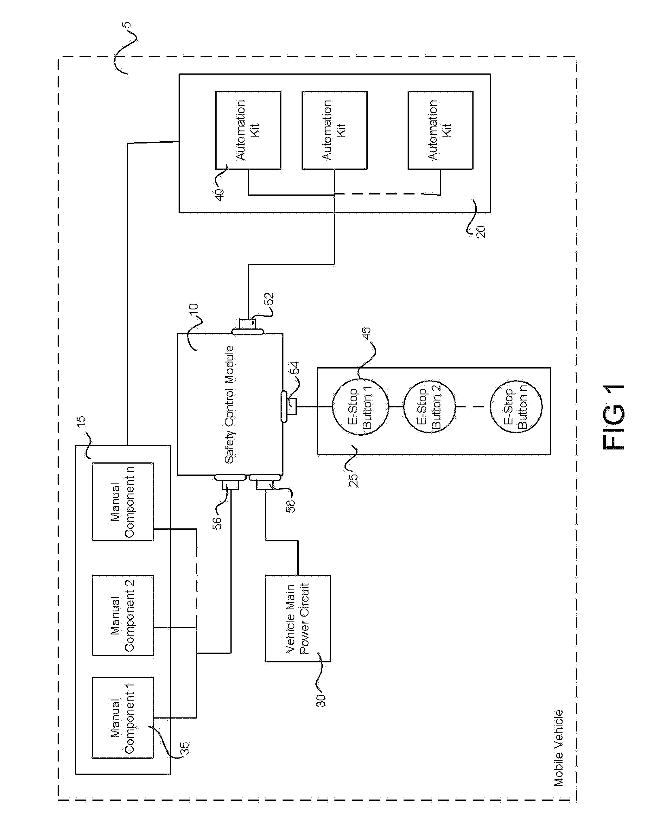
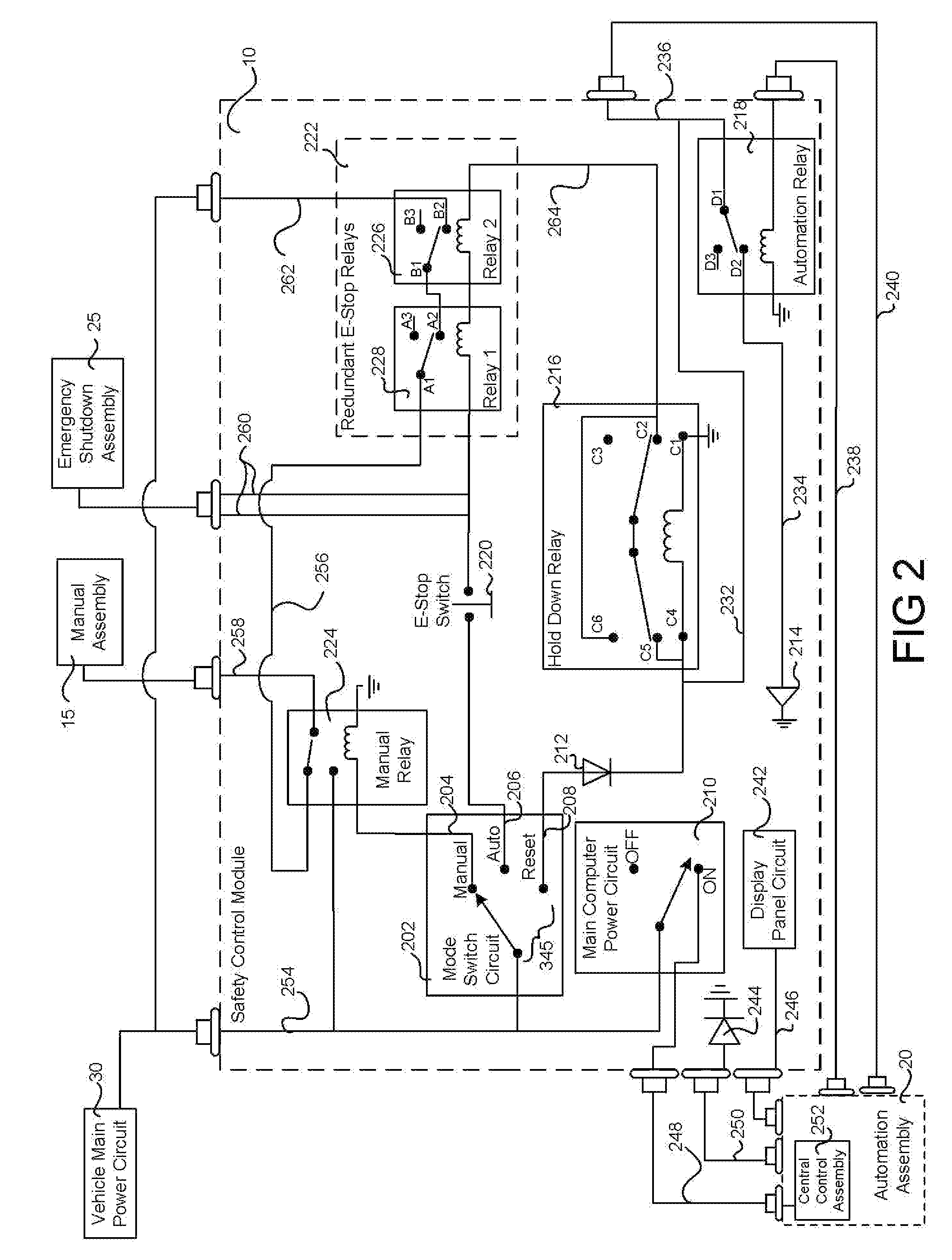
[0020]The safety control module provides a system for controlling distribution of power throughout an automated vehicle. Included within the safety control module is an assembly of circuits and mechanical systems designed to distribute power to the modules and assemblies connected to the safety control module. In particular, the assembly of circuits and mechanical systems distribute power to mechanical systems included in the autonomous vehicle and necessary to operate the autonomous vehicle manually. These mechanical systems receive power from the safety control module when the safety control module operates in a manual mode. When operating in an automatic mode, the mechanical systems receive power in part from an automation assembly connected to the safety control module, and in part from the safety control module....


PUM


Abstract

A robotic assembly comprises: a mobile vehicle including mechanical components configured to operate the mobile vehicle in a manual mode of operation; a main power circuit for distributing a power signal to the electromechanical components and to external modules; an automation module connected to the mechanical components and operable to control and operate the mechanical components, and a power circuit configured to distribute power to the mechanical components and the external modules; a safety control module connected to the main power circuit, the automation module, and the mechanical components; a mode selector connected to the main power circuit; and emergency stop switches configured to prevent a flow of current to substantially all of the mechanical components and external modules in response to actuation of the emergency stop buttons.

Description

INTRODUCTION[0001]This invention relates generally to circuits and assemblies for controlling the flow of power through a semi-autonomous mobile vehicle. In particular, embodiments of this invention relate to multiple mode control modules that control the flow of power through the electrical and mechanical systems included in a semi-autonomous vehicle according to a chosen mode, and a control module that further provides an emergency stop assembly for removing power from substantially all of the electrical and mechanical systems of the semi-autonomous vehicle.BACKGROUND[0002]Safety control systems are included in most process-controlled assemblies to provide the assemblies with the ability to shut down. Multiple types of safety systems exist. Emergency stop safety systems typically operate to remove power from the entire assembly, while other safety systems may stop the flow of liquid or gas, or otherwise stop the process being controlled. Emergency stop safety systems typically fou...

Claims


Application Information

Patent Timeline
Patent Type & Authority Applications(United States)
IPC IPC(8): B25J5/00H02H1/00
CPCB25J19/06B25J13/06
Inventor FITCH, OSA EDWARDWILLIAMS, EDWARD
Owner IROBOT CORP
Why Eureka
Eureka Blog
Learn More