Charger

Inactive Publication Date: 2010-05-13
CHENG UEI PRECISION IND CO LTD
View PDF8 Cites 11 Cited by
  • Summary
  • Abstract
  • Description
  • Claims
  • Application Information

AI Technical Summary

Benefits of technology

[0007]As described above, the rotatable module is pivotally disposed in the base, when the charger is about to charging the mobile phone, the rotatable module is rotated to make the output connector expose out of the cavity. And the mobile phone mates with the output connector and supported by the supporting surface of the basic portion and the base to be charged. When the charging process is completed, the user can hol

Problems solved by technology

It is not conveni

Method used


Image

  • Charger
  • Charger
  • Charger

Examples


Example

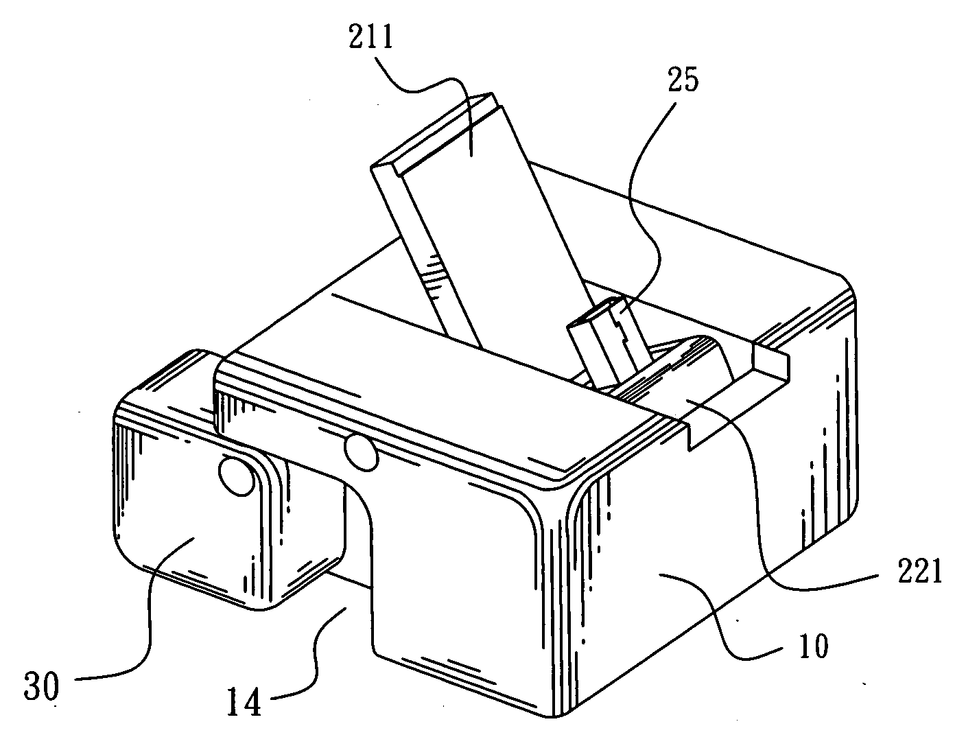
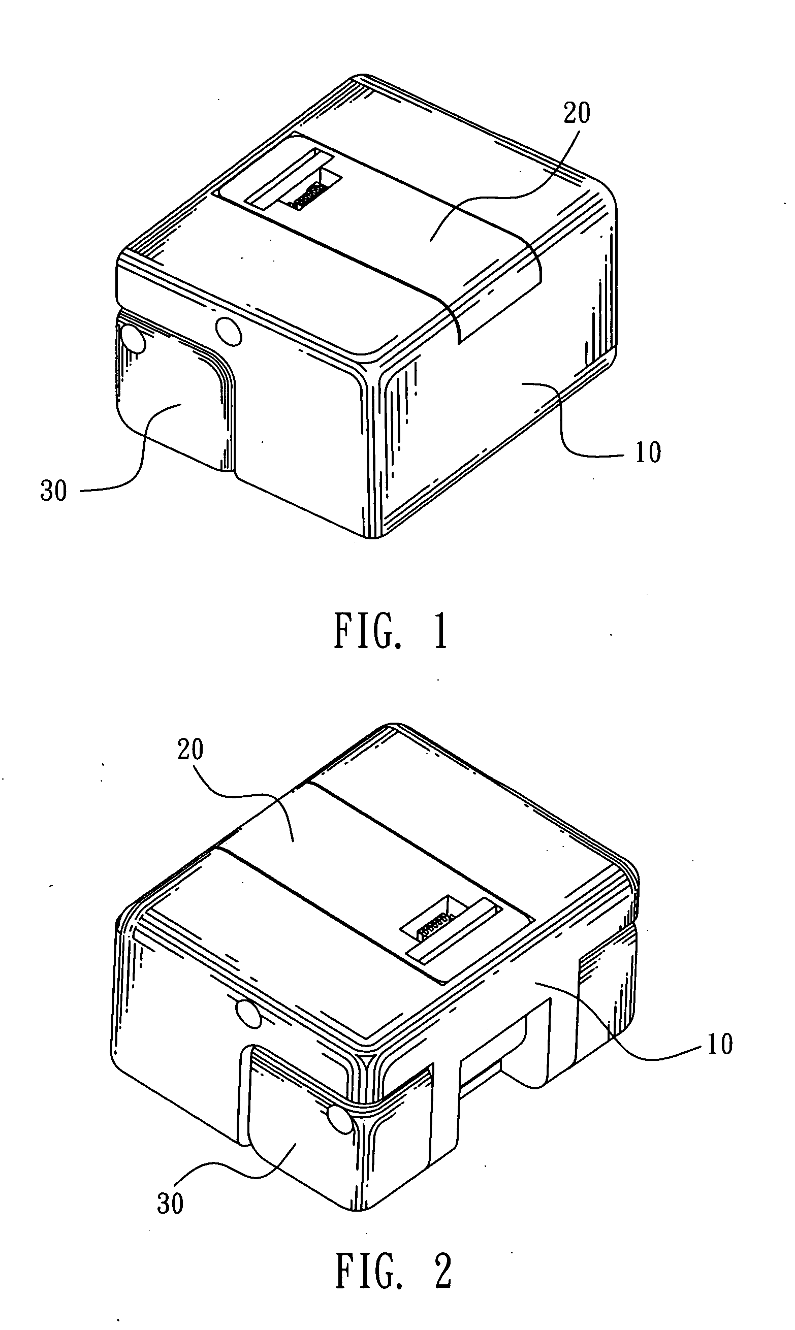
[0031]FIG. 1 and FIG. 2 illustrate a first embodiment of a charger according to the present invention. In this embodiment, the charger includes a base 10, a rotatable module 20, and two supporting elements 30.

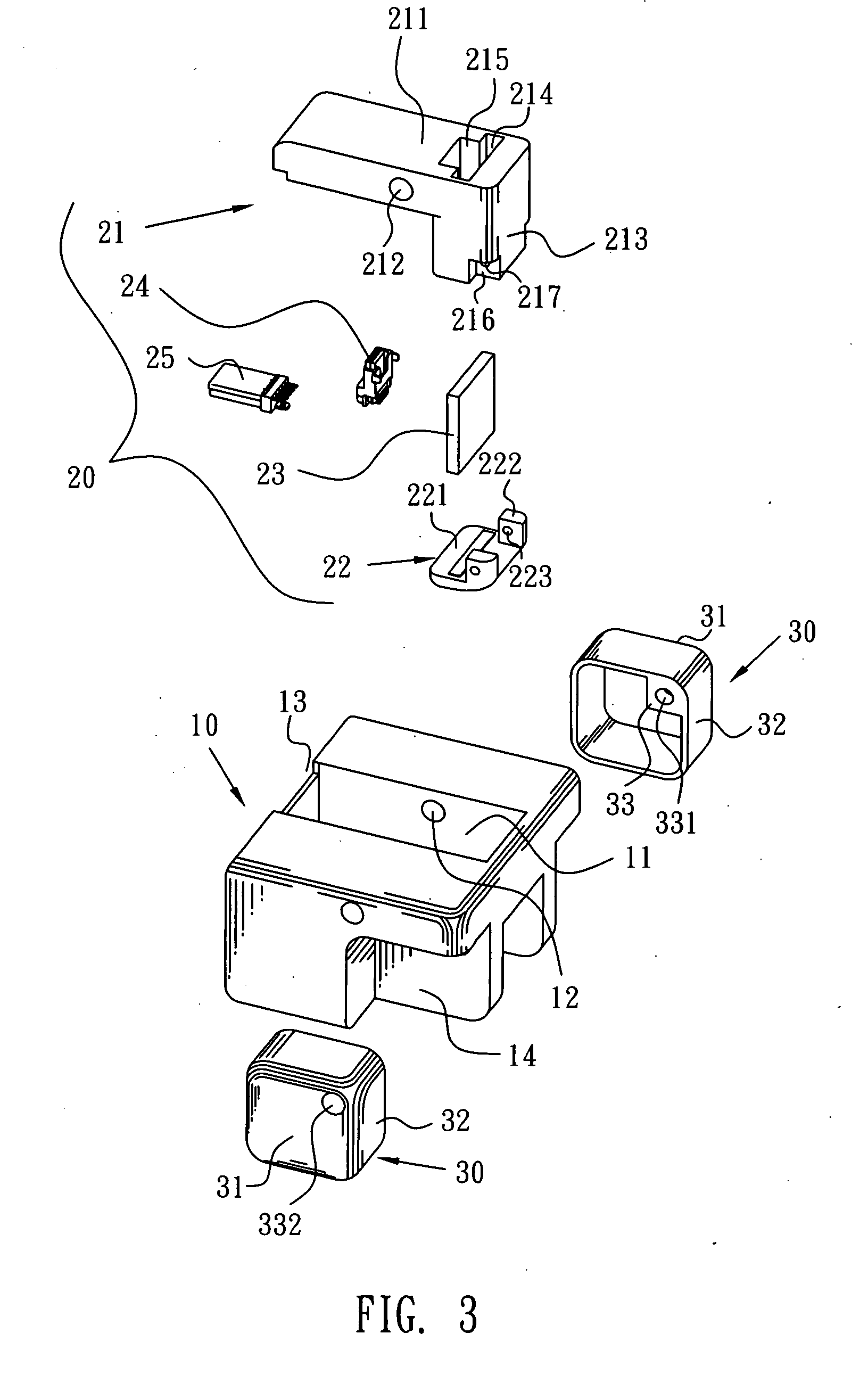
[0032]Please refer to FIG. 3 and FIG. 4, the base 10 is of a substantially rectangular shape. A cavity 11 is defined in the middle of an upper surface of the base 10. Two opposite sides of the cavity 11 respectively define a first hole 12 which communicates with the cavity 11 and penetrates the outer surface of base 10. An indentation 13 is formed in a front end of the base 10 and communicates with the cavity 11. Two sides of a bottom portion of a rear end of the base 10 respectively define a rectangular accommodation space 14. A rear portion of one side of each of the accommodation spaces 14 adjacent to the cavity 11 perpendicularly protrudes into the accommodation space 14 to form a pivot 141. A first fixing hole 142 is formed in a free end of each of the pivots 141.

[0033]Ple...

Example

[0041]Please refer to FIG. 12, a second embodiment of the charger according to the present invention is shown. The second embodiment is similar to the first embodiment. The upper surface of the base 10 defines a supporting groove 15 which is disposed at two sides of the cavity 11 across the cavity 11. The supporting groove 15 includes a first ramp 151 inclining forward from bottom to top and a second ramp 152 inclining rearward from bottom to top.

[0042]When the charger according to the this embodiment is adapted for charging the mobile phone, if the charging connector of the mobile phone is disposed in a lateral side thereof, then the mobile phone will be transversely placed on the charger to make the charging connector of the mobile phone be inserted into the output connector 25 of the rotatable module 20. The lateral side having the charging connector is supported by the first ramp 151; one surface of the mobile phone is supported by the supporting surface 2111 of the basic portio...

Example

[0044]Please refer to FIG. 13 and FIG. 14, a third embodiment of the charger according to the present invention is shown. This embodiment is similar to the second embodiment described above. The upper surface of the base 10 between the front end and the supporting groove 15 is horizontally cut a part to form a section 16 which is disposed lower than the upper surface of the base 10. Two sides of a front end of the main body 21 of the rotatable module 20 extend outward to form a retaining portion 218. A rear side of the retaining portion 218 is a ramp named retaining ramp 219 which inclines forward from top to bottom. When the charger according to this embodiment is in assembly, the retaining portion 218 is placed on the section 16. When the charger is opened, the retaining ramp 219 is supported by the upper surface of the base 10 to ensure the mobile phone is placed on the rotatable module 20 steadily.


PUM


Abstract

A charger adapted for charging a mobile phone includes a base defining a cavity and a rotatable module having a main body. The rotatable module is pivotally disposed in the cavity. The main body has a basic portion and an engaging portion which substantially perpendicularly extends from one end of the basic portion. An output connector is disposed in the engaging portion and extends out of the engaging portion towards the other end of the basic portion to define a mating direction substantially parallel with the basic portion. When the charger is in an opened state for charging, the basic portion is rotated to a predetermined place and the output connector is therefore located out of the cavity; when the mobile phone is taken away from the charger, the output connector returns into the cavity.

Description

BACKGROUND OF THE INVENTION[0001]1. Field of the Invention[0002]The present invention generally relates to a charger, and more particularly to a charger adapted for charging a mobile phone.[0003]2. The Related Art[0004]A conventional charger adapted for charging a mobile phone includes a base. An output connector is disposed in the base for mating with a charging connector of the mobile phone. A recess is formed in a surface of the base and the output connector protrudes from a bottom of the recess and extends into the recess. When the mobile phone is charged by the charger, the mobile phone is inserted into the recess and the charging connector of the mobile phone is electrically connected with the output connector of the charger for charging.[0005]However, the charging process for the mobile phone is completed and the mobile phone is required to be taken out from the charger, as the mobile phone is held in the recess of the charger and the charger connector of the mobile phone is ...

Claims


Application Information

Patent Timeline
IPC IPC(8): H02J7/00
CPCH02J7/0044
Inventor LIN, CHU-GENGCHI, MING-CHIAHSU, TE-HUA
Owner CHENG UEI PRECISION IND CO LTD
Why Eureka
Try Eureka