Optical scanning device, image display device and retinal scanning display

Active Publication Date: 2010-05-13
BROTHER KOGYO KK
View PDF5 Cites 15 Cited by
  • Summary
  • Abstract
  • Description
  • Claims
  • Application Information

AI Technical Summary

Benefits of technology

[0010]The present invention has been made in view of the above-mentioned drawbacks, and it is an object of the present invention to provide an optical scanning device which can preve

Problems solved by technology

That is, when the positional accuracy of the photo detector cannot be ensured, the timing at which the reference signal is generated based on the detection timing of the photo detector is staggered thus giving rise to a drawback that the timing at which the opt

Method used


Image

  • Optical scanning device, image display device and retinal scanning display
  • Optical scanning device, image display device and retinal scanning display
  • Optical scanning device, image display device and retinal scanning display

Examples


embodiment 1

[Constitution of Image Display Device]

[0023]First of all, the constitution of an image display device provided with an optical scanning device is explained.

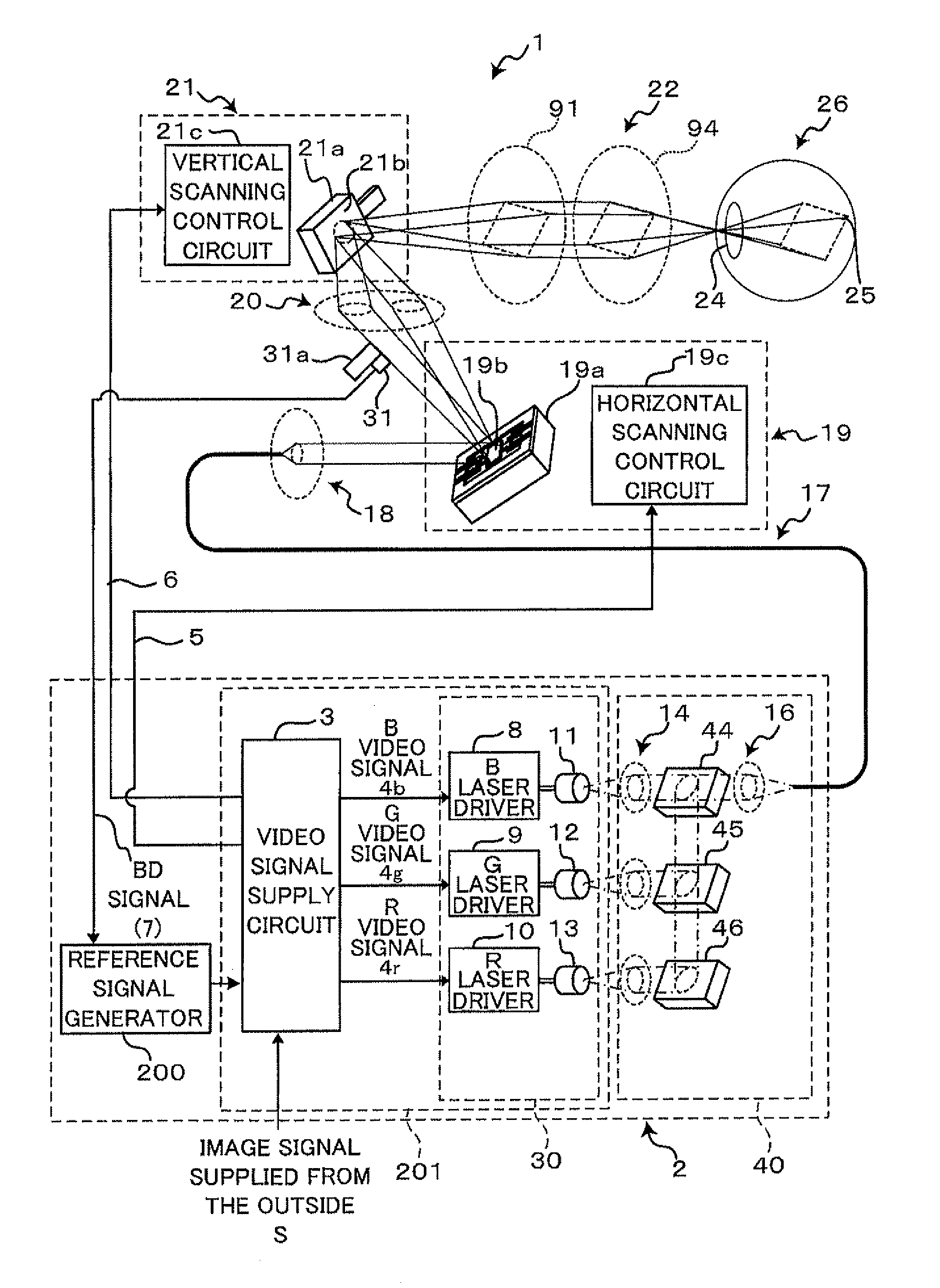
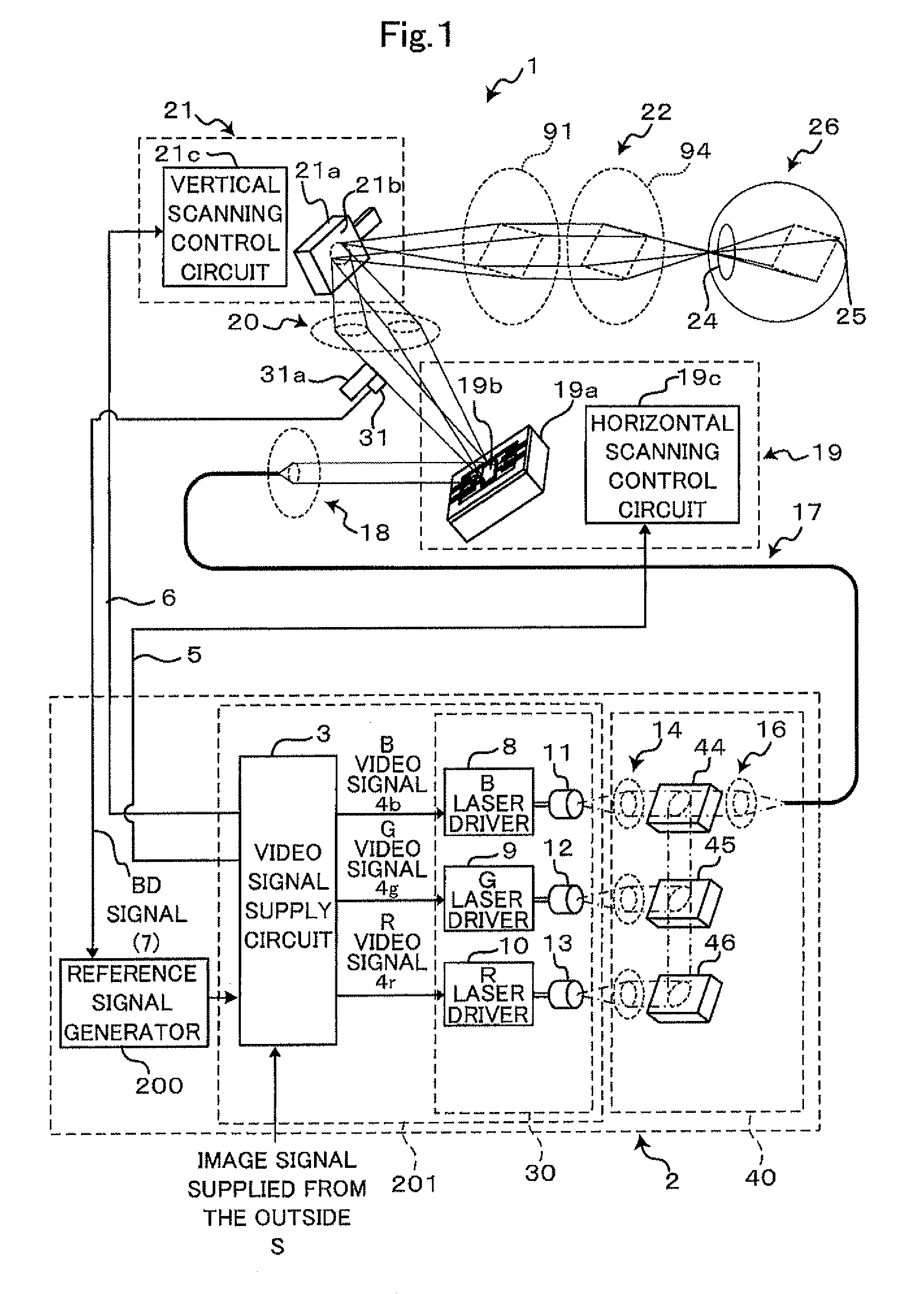
[0024]The image display device 1 is a device in which an optical flux is made incident on a pupil 24 of a viewer who is a user of the image display device 1 so as to project an image on his / her retina 25 thus allowing the viewer to view a virtual image in front of the pupil 24 of a viewer's eye 26. The image display device 1 is also referred to as a retinal scanning display.

[0025]The image display device 1 includes a light source unit 2 which generates an optical flux whose intensity is modulated in response to an image signal S inputted from the outside and radiates the optical flux. As shown in FIG. 1, the light source unit 2 includes a video signal supply circuit 3 to which an image signal S supplied from the outside is inputted and which generates respective signals or the like constituting components for synthesizing an imag...

embodiment 2

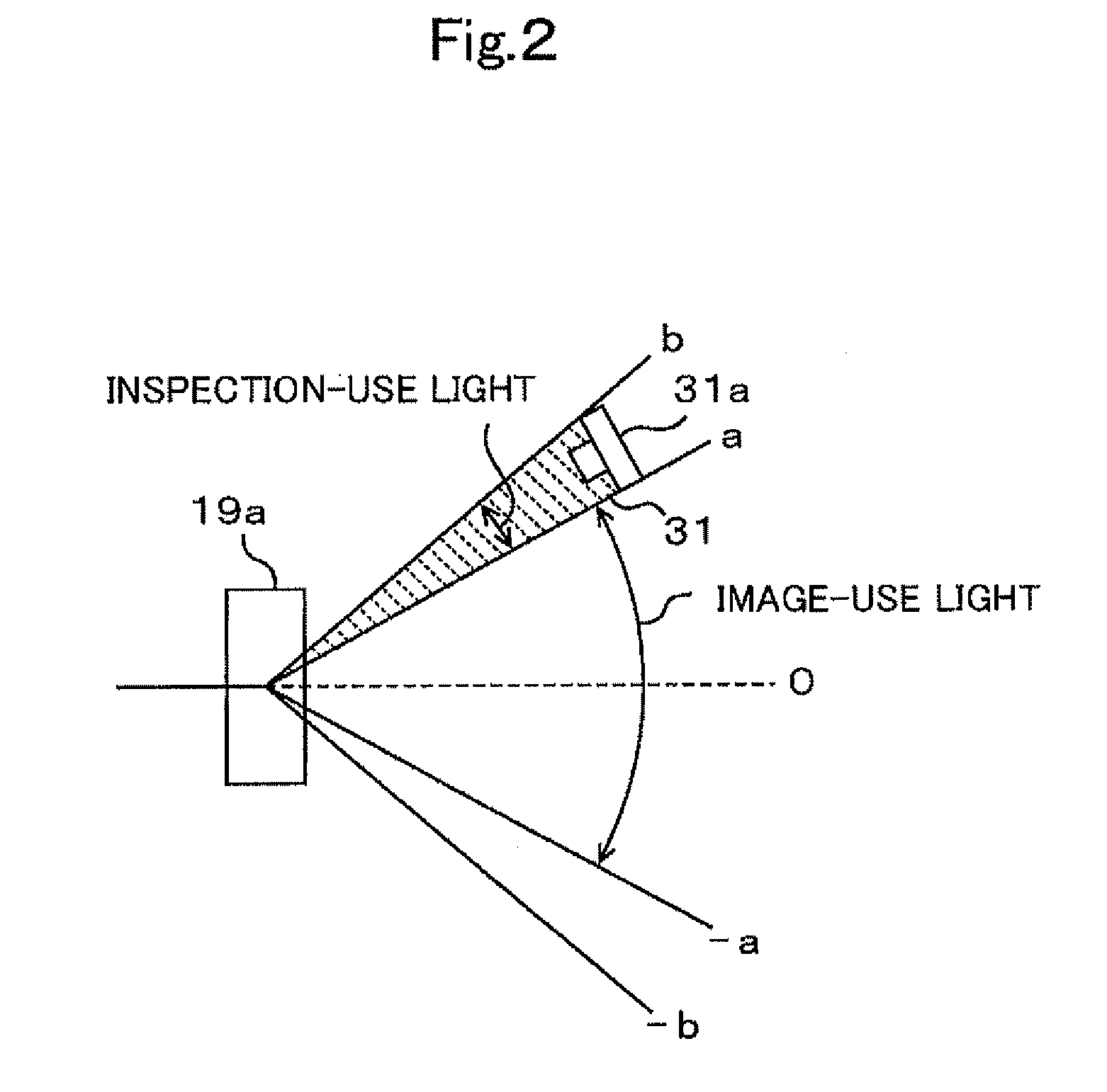
[0076]In the embodiment 1, the photo detector 31 is arranged at the position between the optical scanning element 19a and the vertical scanning part 21. However, the photo detector 31 may be arranged at a position between the vertical scanning part 21 and the relay optical system 22. Hereinafter, the explanation is made with respect to a case where the photo detector 31 is arranged at the position between the vertical scanning part 21 and the relay optical system 22 in conjunction with FIG. 7 to FIG. 9. Symbols used in FIG. 7 to FIG. 9 are equal to the symbols used in FIG. 1 to FIG. 6 with respect to constitutional elements identical with the constitutional elements shown in FIG. 1 to FIG. 6.

[0077]In the embodiment 2, as shown in FIG. 7, the photo detector 31 is arranged at the position between the vertical scanning part 21 and the relay optical system 22. That is, as shown in FIG. 8A, the photo detector 31 is arranged at a position where an inspection light can be detected, wherein...


PUM


Abstract

An optical scanning device includes an optical scanning element which has a reflection mirror and is configured to perform reciprocating scanning of an optical flux radiated from a light source by resonance oscillations of the reflection mirror; a photo detector which is arranged at a position which a portion of the optical flux scanned by the optical scanning element in a reciprocating manner passes in both outgoing-path scanning and incoming-path scanning, and is configured to output a pulse signal having a predetermined width at a point of time that the scanned optical flux is detected; and the reference signal generator which is configured to detect timing between rising edge timing of one pulse signal and falling edge timing of the other pulse signal out of two pulse signals continuously outputted from the photo detector, and to generate the reference signal based on intermediate timing between the edge timings.

Description

CROSS-REFERENCE TO RELATED APPLICATIONS[0001]The present application is a Continuation-in-Part of International Application PCT / JP2008 / 061700 filed on Jun. 27, 2008, which claims the benefits of Japanese Patent Application No. 2007-173465 filed on Jun. 29, 2007.BACKGROUND[0002]1. Field[0003]The present invention relates to an optical scanning device, an image display device provided with the optical scanning device, and a retinal scanning display provided with the optical scanning device.[0004]2. Description of the Related Art[0005]Conventionally, an optical scanning device has been used in a laser printer device, a projection device or the like. This optical scanning device uses an optical scanning element having a reflection mirror which scans an optical flux by oscillations. The optical flux scanned by the optical scanning element is projected on a projection surface such as a screen so that an image is formed on the projection surface, or the scanned optical flux is projected on...

Claims


Application Information

Patent Timeline
IPC IPC(8): G02B26/10
CPCG02B26/101G09G3/02H04N9/3129G09G2340/0464G09G2360/145G09G5/18
Inventor TAKAYAMA, HARUHISA
Owner BROTHER KOGYO KK
Why Eureka
Try Eureka