Optical Safety Implementation in Protection Switching Modules

a technology of optical safety and protection switching, applied in the field of optical networks, can solve the problems of optical networks that have problems in implementing protection and safety measures, power of lasers used in optical networks is relatively low, and the effect of affecting the safety of optical networks

Active Publication Date: 2010-05-13
CISCO TECH INC
View PDF5 Cites 30 Cited by
  • Summary
  • Abstract
  • Description
  • Claims
  • Application Information

AI Technical Summary

Problems solved by technology

While the lasers used in optical networks have relatively low power compared to, for example, industrial lasers, they are powerful enough to damage the human eye.
However, optical networks still have problems in implementing protection and safety measures.

Method used


Image

  • Optical Safety Implementation in Protection Switching Modules
  • Optical Safety Implementation in Protection Switching Modules
  • Optical Safety Implementation in Protection Switching Modules

Examples


example embodiments

DESCRIPTION OF EXAMPLE EMBODIMENTS

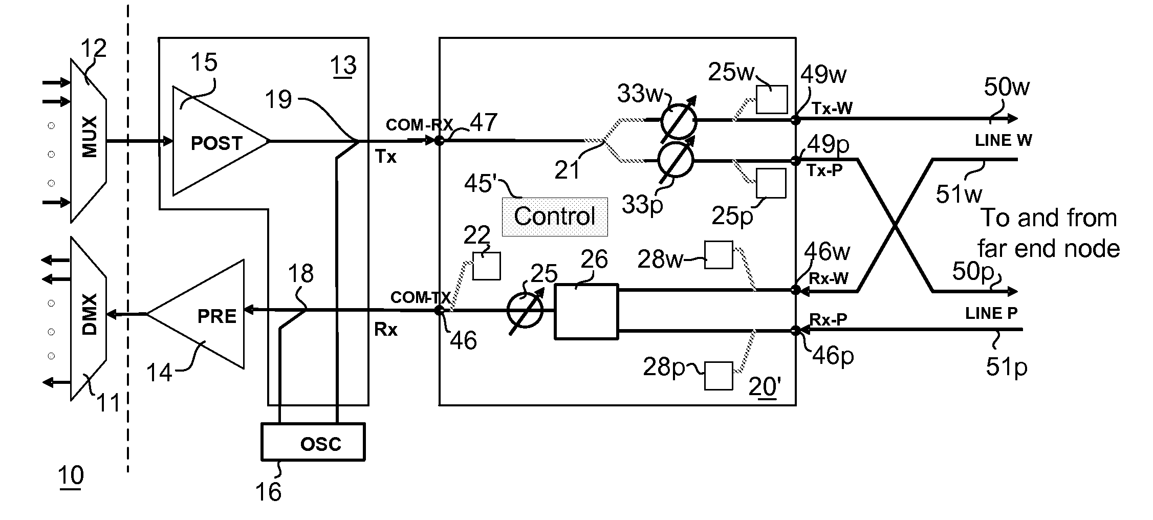
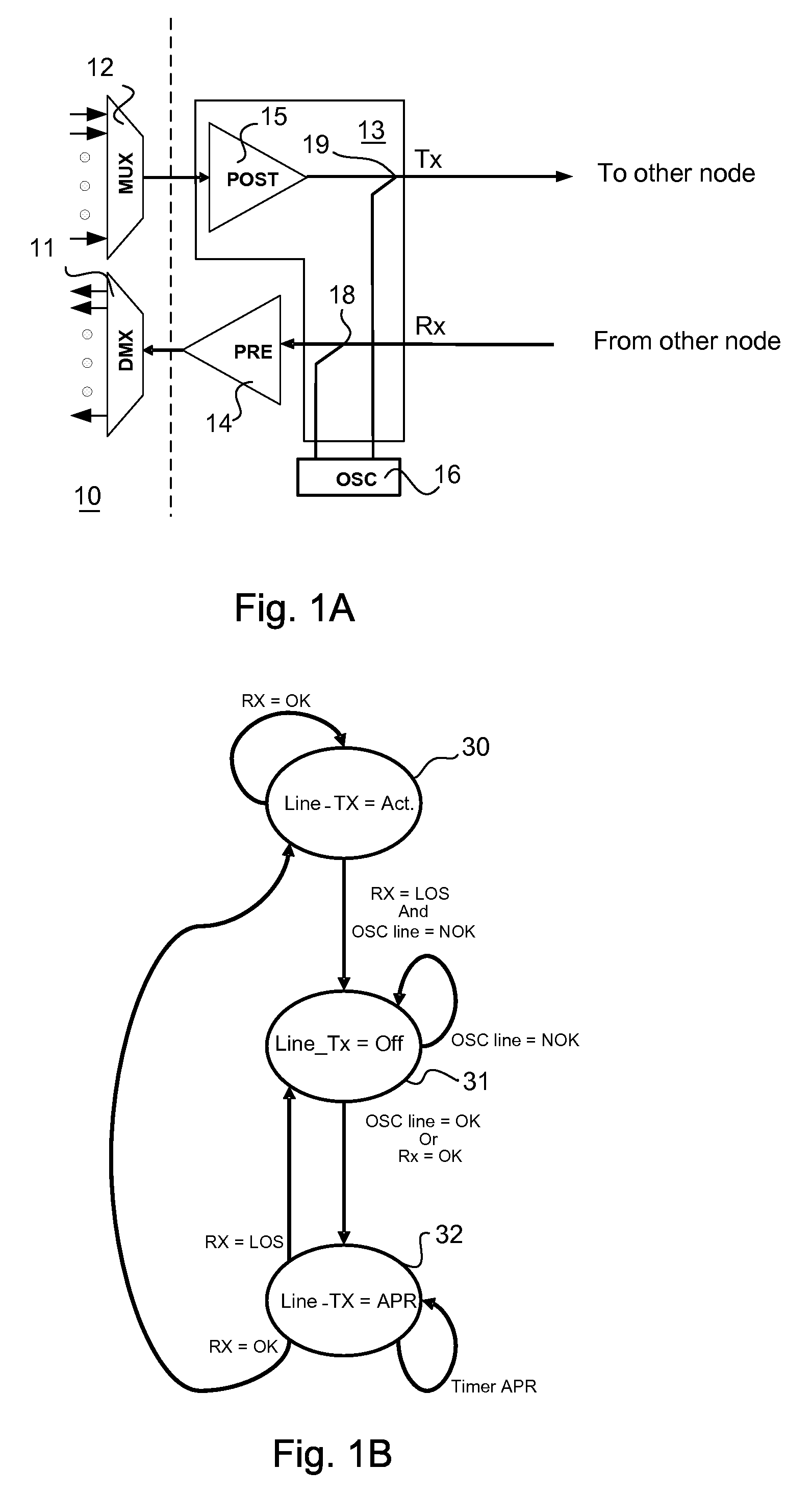
[0016]FIG. 1A illustrates a node 10 connected to another node (not shown) at the remote end of an exemplary two-fiber link, which forms a fiber loop between the two nodes. The node 10 is represented by a multiplexer 12 which gathers signals from various sources to transmit to the remote node by a Tx fiber and a demultiplexer 11 which separates signals received from the remote node by an Rx fiber for various destinations.

[0017]Optical signals deteriorate as they travel through optical networks and must be periodically amplified. To this end optical amplifiers are installed at different locations of an optical network to ensure that optical signals are not lost. In the exemplary and conventional arrangement of FIG. 1A, a pre-amplifier 14 boasts the strength of incoming signals received through the Rx input port over the Rx line before passing the signals to the node 10. For signals leaving the node 10, a post-amplifier 15 boasts signal strength of sig...


PUM


Abstract

Optical safety functions are incorporated into protection switching modules which maintain redundant pathways to avoid interruptions in optical network connections. The optical safety functions which lower optical power levels upon interruptions of optical connections are effectively combined with protection switching procedures which are also triggered by interruptions in optical network connections. The interoperation of protection and safety processes keep optical power levels below hazardous levels at system points which might be accessible to human operators.

Description

BACKGROUND OF THE INVENTION[0001]The present invention is related to optical networks and, more particularly to, safety and protection measures and procedures in such networks.[0002]When a fault occurs in the transmission of signals from a source node to a destination node, such as a break in an optical fiber, the protection measures of the optical network cause the rerouting of the signals to ensure the delivery of optical signals to their destination. There are different ways to protect optical networks against faults. One protection mechanism used in point-to-point links is the 1+1 mechanism in which the source node sends duplicate signals on two separate fibers to the destination node. The destination node receives the optical signals over one fiber, called the working fiber, and switches to the other fiber, called the protection fiber, in case a fault occurs with the first fiber to continue receiving the signals. Another protection mechanism is the 1:1 mechanism (a special case...

Claims


Application Information

Patent Timeline
Patent Type & Authority Applications(United States)
IPC IPC(8): H04B10/00
CPCH04B10/032H04B10/0773H04Q2011/0081H04Q11/0062H04Q2011/0079H04B2210/08
Inventor FERRARI, CINZIATANZI, ALBERTO
Owner CISCO TECH INC
Why Eureka
Try Eureka