Method and system for converting waste heat from cement plant into a usable form of energy

a technology of waste heat and energy, which is applied in the direction of steam generation using hot heat carriers, machines/engines, mechanical equipment, etc., can solve the problem of limiting the final temperatur

Active Publication Date: 2010-05-20
KALINA POWER LTD +1
View PDF6 Cites 45 Cited by
  • Summary
  • Abstract
  • Description
  • Claims
  • Application Information

AI Technical Summary

Benefits of technology

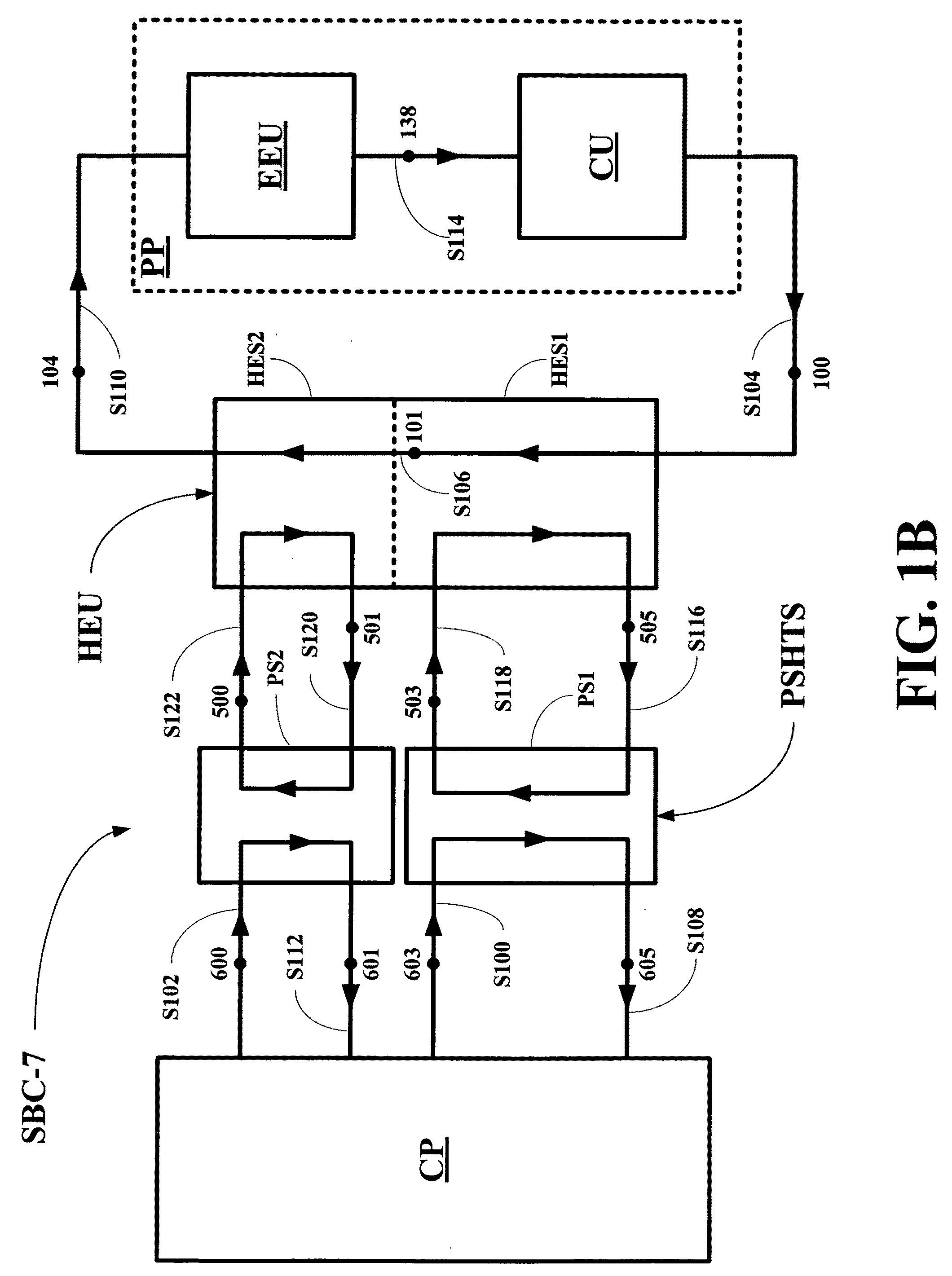
[0021]In other embodiments, the method further includes: (1) passing the hot air stream through a large particle separator of a particulate separation and heat transfer subsystem to form a dust laden hot air stream, (2) pressurizing the dust laden hot air stream to form a higher pressure, dust laden hot air stream, (3) filtering the higher pressure, dust laden hot air stream to form a substantially dust free, higher pressure, hot air stream, and (4) transferring heat from the substantially dust free, higher pressure, hot air stream to a first high temperature heat transfer fluid stream in a scrubber to form the cooled air stream and a heated first high temperature heat transfer fluid stream, which is used to partially vaporize the fully condensed, multi-component working fluid stream in the first stage of the heat exchange unit.
[0022]In other embodiments, the method further includes (5) pressurizing the heated first high temperature heat transfer fluid stream to form a higher pressure, heated first high temperature heat transfer fluid stream, before being forwarded to the first stage of the heat exchange unit.
[0023]In other embodiments, the method further includes: (1) passing the flue gas stream through a large particle separator of a particulate separation and heat transfer subsystem to form a dust laden flue gas stream, (2) pressurizing the dust laden flue gas stream to form a higher pressure, dust laden flue gas stream, (3) filtering the higher pressure, dust laden flue gas stream to form a substantially dust free, higher pressure, flue gas stream, and (4) transferring heat from the substantially dust free, higher pressure, flue gas stream to a second high temperature heat transfer fluid stream in a scrubber to form the cooled flue gas stream and a heated second high temperature heat transfer fluid stream, which is used to fully vaporize and superheat the partially vaporized, multi-component working fluid stream in the second stage of the heat exchange unit.
[0024]In other embodiments, the method further includes (5) pressurizing the heated second high temperature heat transfer fluid stream to form a higher pressure, heated second high temperature heat transfer fluid stream, before being forwarded to the second stage of the heat exchange unit.
[0025]In other embodiments, the method further includes: (1) passing the hot air stream through a large particle separator of a particulate separation and heat transfer subsystem to form a dust laden hot air stream, (2) pressurizing the dust laden hot air stream to form a higher pressure, dust laden hot air stream, (3) filtering the higher pressure, dust laden hot air stream to form a substantially dust free, higher pressure, hot air stream, (4) transferring heat from the substantially dust free, higher pressure, hot air stream to a first high temperature heat transfer fluid stream in a scrubber to form the cooled air stream and a heated first high temperature heat transfer fluid stream, which is used to partially vaporize the fully condensed, multi-component working fluid stream in the first stage of the heat exchange unit, (5) passing the flue gas stream through a large particle separator of a particulate separation and heat transfer subsystem to form a dust laden flue gas stream, (6) pressurizing the dust laden flue gas stream to form a higher pressure, dust laden flue gas stream, (7) filtering the higher pressure, dust laden flue gas stream to form a substantially dust free, higher pressure, flue gas stream, and (8) transferring heat from the substantially dust free, higher pressure, flue gas stream to a second high temperature heat transfer fluid stream in a scrubber to form the cooled flue gas stream and a heated second high temperature heat transfer fluid stream, which is used to fully vaporize and superheat the partially vaporized, multi-component working fluid stream in the second stage of the heat exchange unit.
[0026]In other embodiments, the method further includes: (9) pressurizing the heated first high temperature heat transfer fluid stream to form a higher pressure, heated first high temperature heat transfer fluid stream, before being forwarded to the first stage of the heat exchange unit, and (10) pressurizing the heated second high temperature heat transfer fluid stream to form a higher pressure, heated first high temperature heat transfer fluid stream, before being forwarded to the second stage of the heat exchange unit.

Problems solved by technology

This type of system imposes a limit on the final temperature to which the flue gas can be cooled in a power system.

Method used


Image

  • Method and system for converting waste heat from cement plant into a usable form of energy
  • Method and system for converting waste heat from cement plant into a usable form of energy
  • Method and system for converting waste heat from cement plant into a usable form of energy

Examples


embodiment

FIG. 1A Embodiment

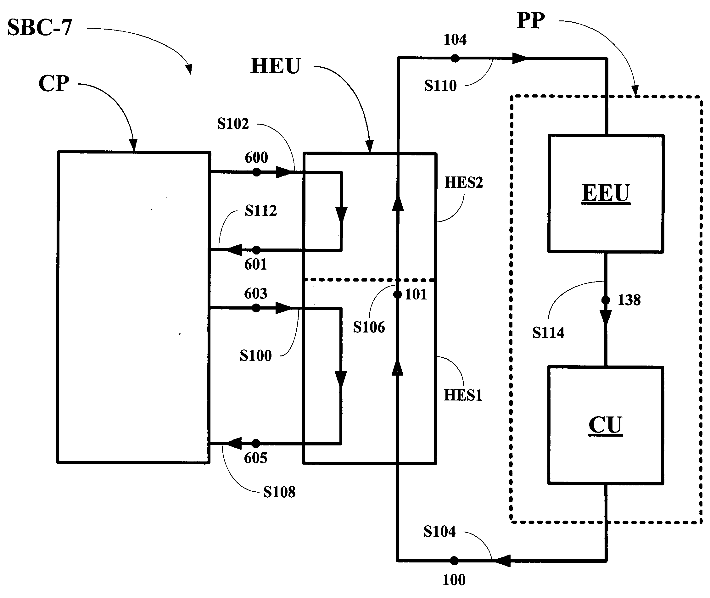
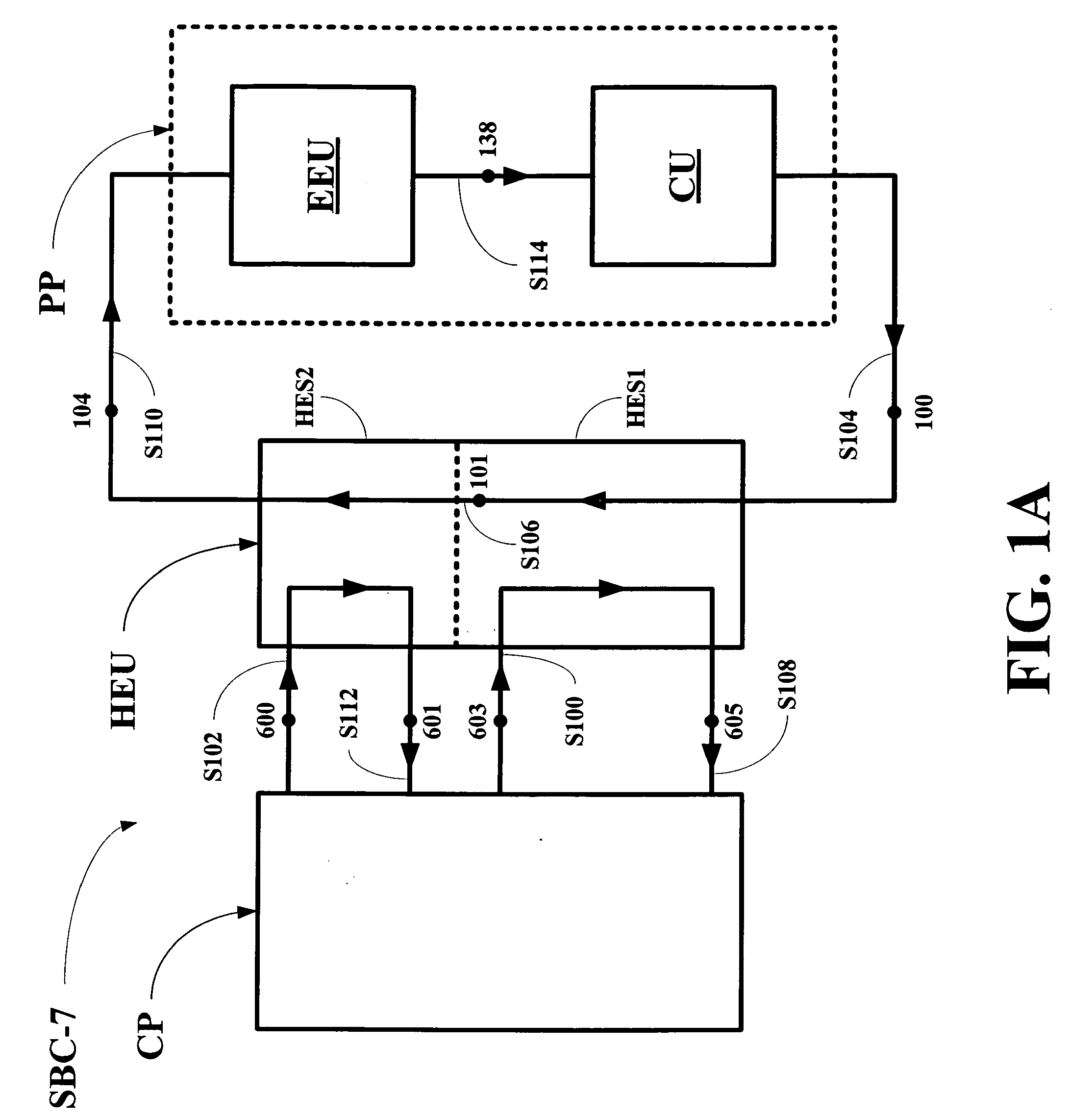
[0044]Referring now to FIG. 1A, an embodiment of a system of this invention, generally SBC-7, is shown to include a cement plant CP, a heat exchange unit HEU, and a power plant PP. The cement plant CP produces two heat sources stream, a hot air stream S100 having parameters as at a point 603 and a flue gas stream S102 having parameters as at a point 600.

[0045]The hot air stream S100 having the parameters as at the point 603 passes through a first stage HES1 of the heat exchange unit HEU in counterflow with a fully condensed, multi-component working fluid stream S104 having parameters as at a point 100 in a first heat exchange process 603-605 or 100-101. The stream S104 having the parameters as at the point 100 is partially vaporized to form a partially vaporized working fluid stream S106 having parameters as at a point 101 and a cooled air stream S108 having parameters as at a point 605.

[0046]The flue gas stream S102 having the parameters as at the point 600 passes...

##s embodiment

FIG. 3A PSHTS Embodiment

[0074]Referring now to FIG. 3A, the hot air stream S100 having parameters as at a point 603 or the flue gas stream S102 having the parameters as at the point 600 from the cement plant CP passes through the cyclone separator C, where large particles of dust are separated from the hot air stream S100 having the parameters as at the point 603 or the flue gas stream S102 having the parameters as at the point 600 by centripetal forces to form a partially cleaned hot air stream S136 having parameters as at a point 612 or a partially cleaned flue gas stream S138 having parameters as at a point 610. One experienced in the art can easily select a proper type and design of the cyclone separator C for this purpose.

[0075]Thereafter, the partially cleaned hot air stream S136 having the parameters as at the point 612 or the partially cleaned flue gas stream S138 having parameters as at a point 610, still carrying a substantial quantity of dust, is sent into a bottom port 2...


PUM

PropertyMeasurementUnit
thermal energyaaaaaaaaaa
temperatureaaaaaaaaaa
energyaaaaaaaaaa

Abstract

Methods and systems for converting waste heat from cement plant into a usable form of energy are disclosed. The methods and systems make use of two heat source streams from the cement plant, a hot air stream and a flue gas stream, to fully vaporize and superheat a working fluid stream, which is then used to convert a portion of its heat to a usable form of energy. The methods and systems utilize sequential heat exchanges stages to heat the working fluid stream, first with the hot air stream or from a first heat transfer fluid stream heated by the hot air stream and second with the flue gas stream from a second heat transfer fluid stream heated by the hot air stream.

Description

BACKGROUND OF THE INVENTION[0001]1. Field of the Invention[0002]The present invention, generally, relates to a system and method for the effective utilization of waste heat from cement kilns to produce usable forms of power.[0003]More particularly, the present invention, generally, relates to a system and method for the effective utilization of waste heat from cement kilns to produce usable forms of power, where the system includes a cement plant CP, a heat exchange unit HEU having sequential heat exchanges stages for transferring heat from two heat source stream produced by the cement plant CP, and a power plant PP.[0004]2. Description of the Related Art[0005]Usually, cement kilns produce two streams of waste heat; a stream of flue gas and a stream of hot air. The flow rate of the flue gas is usually larger than the flow rate of the hot air. The initial temperature of the flue gas is higher than the initial temperature of the hot air. In a typical application of this sort, the stre...

Claims


Application Information

Patent Timeline
Patent Type & Authority Applications(United States)
IPC IPC(8): F01K13/00C04B7/36
CPCC04B7/43C04B7/475F22B1/18F01K25/10F01K25/06Y02P40/121
Inventor KALINA, ALEXANDER I.
Owner KALINA POWER LTD
Why Eureka
Try Eureka