Intake For Shrouded Electric Submersible Pump Assembly

a technology of electric submersible pumps and pump assemblies, which is applied in the direction of fluid removal, earthwork drilling and mining, and well accessories, etc., can solve the problems of high failure rate, motor lead cable can represent a major failure mode, and the pump intake pressure of the pump cannot be below the fluid bubble point pressure, etc., to achieve the effect of reducing the space within the shroud

Active Publication Date: 2010-05-20
SAUDI ARABIAN OIL CO
View PDF8 Cites 26 Cited by
  • Summary
  • Abstract
  • Description
  • Claims
  • Application Information

AI Technical Summary

Benefits of technology

[0006]An electric submersible pump (ESP) assembly comprises an integrated sub-assembly encased within a shroud. The integrated sub-assembly comprises a downhole monitoring gauge, a motor, a well fluid intake, a seal section, a mounting member, and an electrical conduit. The intake, seal section, motor, and monitoring gauge are connected to an under side of the mounting member. The intake has a plurality of intake slots positioned a select distance from the under side of the mounting member in order to minimize the space within the shroud for the accumulation of gas.

Problems solved by technology

In these applications, the penetrator system and the lower motor lead cable can represent a major failure mode for the ESP.
Often, a high percentage of failures are directly related to the packer penetrator, motor lead cable, or motor pot head.
Additionally, as the packer above the ESP creates a pressure boundary in the annulus, ESP's can not produce with pump intake pressures below the fluid bubble point pressure without creating gas pockets below the packer.
This phenomenon often causes operators to reduce production rates from a well as draw downs are restricted to maintain certain pump intake pressures.
As a result, pump intake pressures at or below bubble point pressures are not desirable.

Method used


Image

  • Intake For Shrouded Electric Submersible Pump Assembly
  • Intake For Shrouded Electric Submersible Pump Assembly
  • Intake For Shrouded Electric Submersible Pump Assembly

Examples


Embodiment Construction

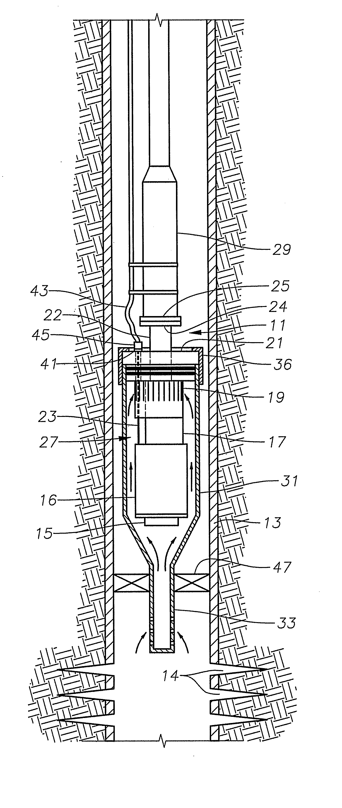
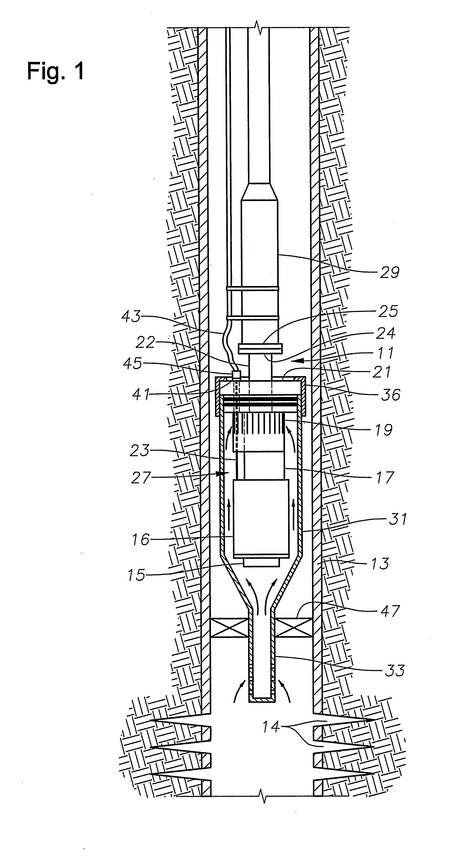
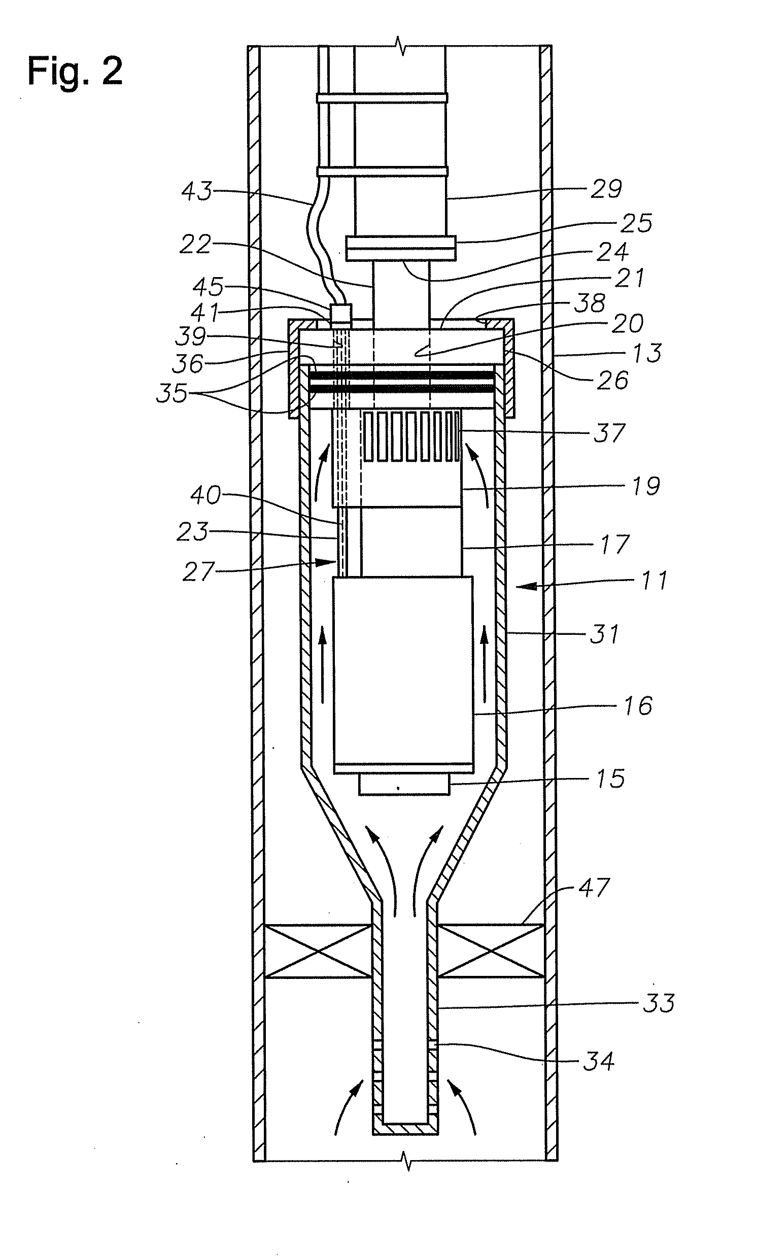
[0013]FIG. 1 shows a completed well with a downhole, electric submersible pump (ESP) assembly 11 lowered down the casing 13 to above the perforations 14 in the well. The well produces a mixture of viscous oil and water. Referring to FIG. 2, ESP assembly 11 comprises a downhole monitoring gauge or sensor 15, a motor 16, a seal section 17, a well fluid intake 19, a mounting member 21, an electrical conduit 23, and a connector flange 25, all of which are supplied pre-assembled and form an integral sub-assembly 27. In one embodiment, sensor 15 may provide motor temperature, ambient temperature, and pressure readings. Mounting member 21 is a cylindrical tubular member joined on its lower side to intake 19. Mounting member 21 has an upper flange portion 26 having a greater diameter than a lower portion. Mounting member 21 has an axial passage 20 extending therethrough. Mounting member 21 has a tubular neck 22 joined to upper flange portion 26 and extending upward. Neck 22 has a flange 24 ...


PUM


Abstract

An electric submersible pump (ESP) assembly comprises an integrated sub-assembly encased within a shroud. The integrated sub-assembly comprises a downhole monitoring gauge, a motor, a well fluid intake, a seal section, a mounting member, and an electrical conduit extending between the mounting member and the motor. The intake has a plurality of intake slots positioned a select distance from the mounting member in order to minimize the space for the accumulation of gas within the shroud. The electrical conduit sealingly extends through the mounting member to a receptacle located on an upper portion thereof. Conductors are encased within the conduit and are connected between the receptacle and the motor. The conduit prevents the conductors from being affected by reservoir fluid and pressures.

Description

[0001]This application claims priority to provisional application 61 / 114,810, filed Nov. 14, 2008.FIELD OF THE INVENTION[0002]This disclosure relates in general to electric submersible pump assemblies and in particular to shrouded electric submersible pump assemblies.BACKGROUND OF THE INVENTION[0003]In many electric submersible pump (ESP) operations, deep set packers are required to protect casing annulus from contact with reservoir fluid and as a barrier for well control. In these cases, the ESP is located below the packer, which requires a packer penetrator system to be used to connect the ESP's electrical power cable above the packer to the motor lead cable below. In these applications, the penetrator system and the lower motor lead cable can represent a major failure mode for the ESP. Often, a high percentage of failures are directly related to the packer penetrator, motor lead cable, or motor pot head. Additionally, as the packer above the ESP creates a pressure boundary in the...

Claims


Application Information

Patent Timeline
Patent Type & Authority Applications(United States)
IPC IPC(8): E21B43/00
CPCE21B43/128
Inventor ROOKS, MARK K
Owner SAUDI ARABIAN OIL CO
Why Eureka
Try Eureka