
Electromagnetic drive with a lifting armature

a technology of electromagnetic drive and lifting armature, which is applied in the direction of valve details, electrical equipment, basic electric elements, etc., can solve the problem of not allowing a flexible use of components in different combinations, and achieve the effect of high magnetic for

Inactive Publication Date: 2010-05-20
BURKERT WERKE
View PDF18 Cites 13 Cited by
  • Summary
  • Abstract
  • Description
  • Claims
  • Application Information

AI Technical Summary

Benefits of technology

[0007]According to another embodiment of the invention, the yoke rod has a diameter which is reduced relative to the diameters of the yoke stud and the core plug, and the solenoid coil surrounding the yoke rod has a correspondingly increased winding volume. This measure also increases the attainable magnetic forces. The reduced diameter of the yoke rod may be compensated for by using high-quality soft iron.
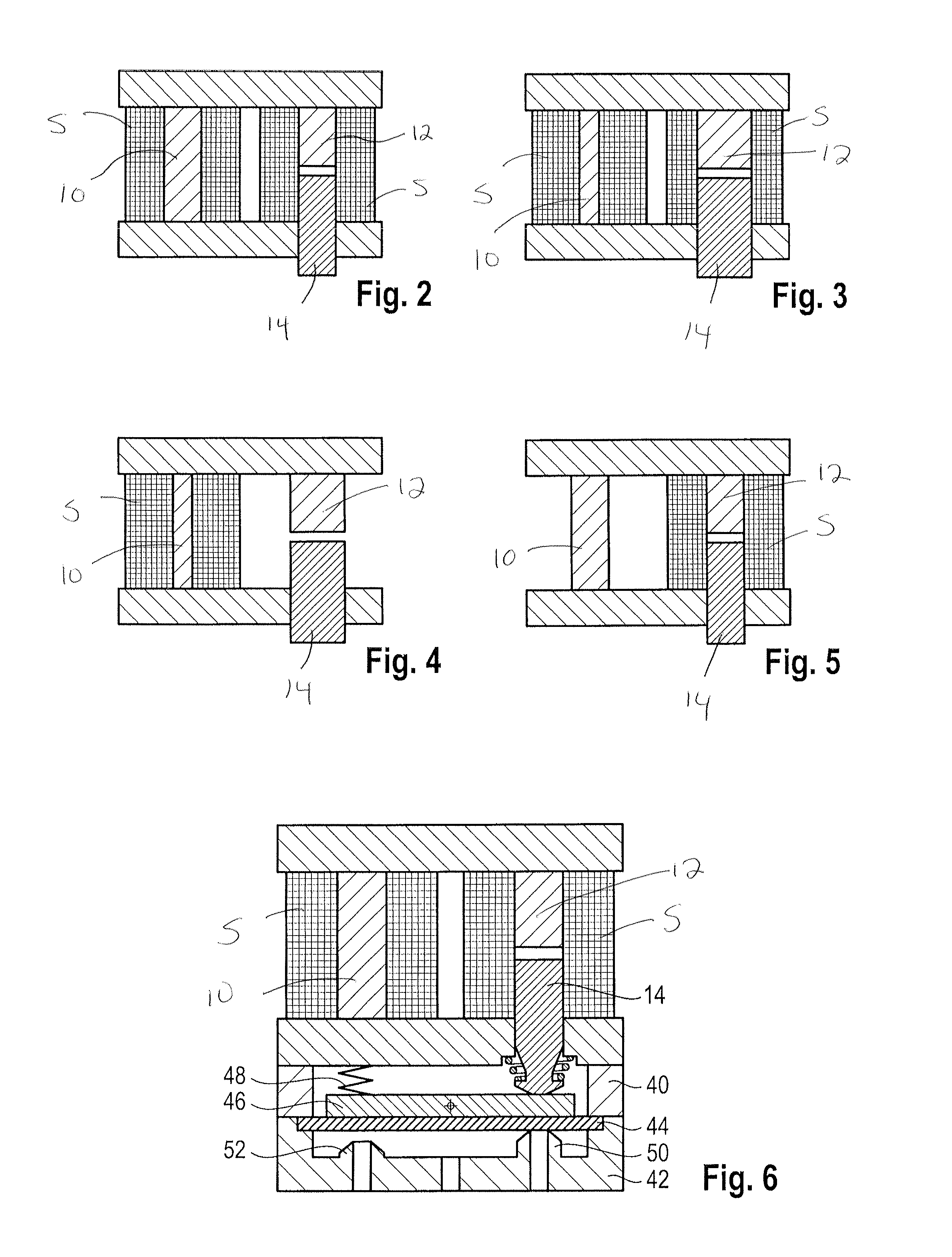
[0008]Various designs of solenoid coils, yoke rods, yoke legs, yoke studs and core plugs may be freely combined in an advantageous manner.
[0015]When two solenoid coils are used, an overexcitation may be produced in a simple manner by changing over between a parallel connection and a series connection.
[0017]In the area of the lifting armature, it is possible to apply all of the specifications as with simple lifting armature systems, namely, a thrust cone for proportional solenoids and switching magnets, a short-circuit ring for alternating current versions, permanent magnets for pulse variants, a pole sleeve, or a pole piece for improving the flux conduction.
[0022]For optimizing the magnetic force, the parts which are in contact with the medium, i.e. the yoke stud and the core plug, that are used here are made of nobler steels not susceptible to corrosion, which are less favorable magnetically, but, to make up for that, they are produced with larger diameters. This iron cross-section is thus increased on the part of the valve actuating element. The stationary yoke rod, which is not in contact with the medium, is produced from a material having good magnetizability. Its cross-section may be selected to be smaller, as a result of which more coil space is available.

Problems solved by technology

But the yoke design proposed there does not allow a flexible use of the components in different combinations.

Method used


Image

  • Electromagnetic drive with a lifting armature
  • Electromagnetic drive with a lifting armature
  • Electromagnetic drive with a lifting armature

Examples


Embodiment Construction

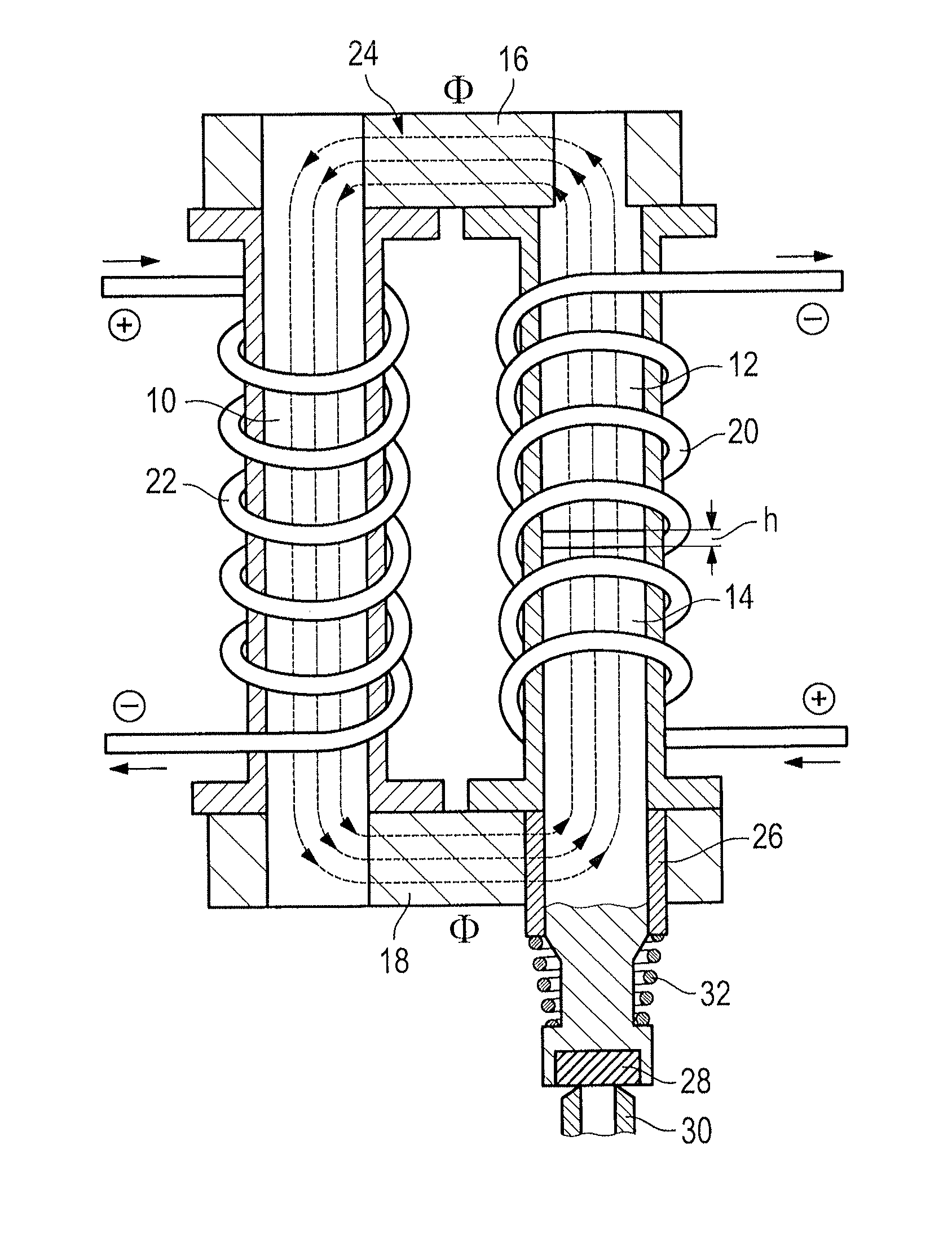
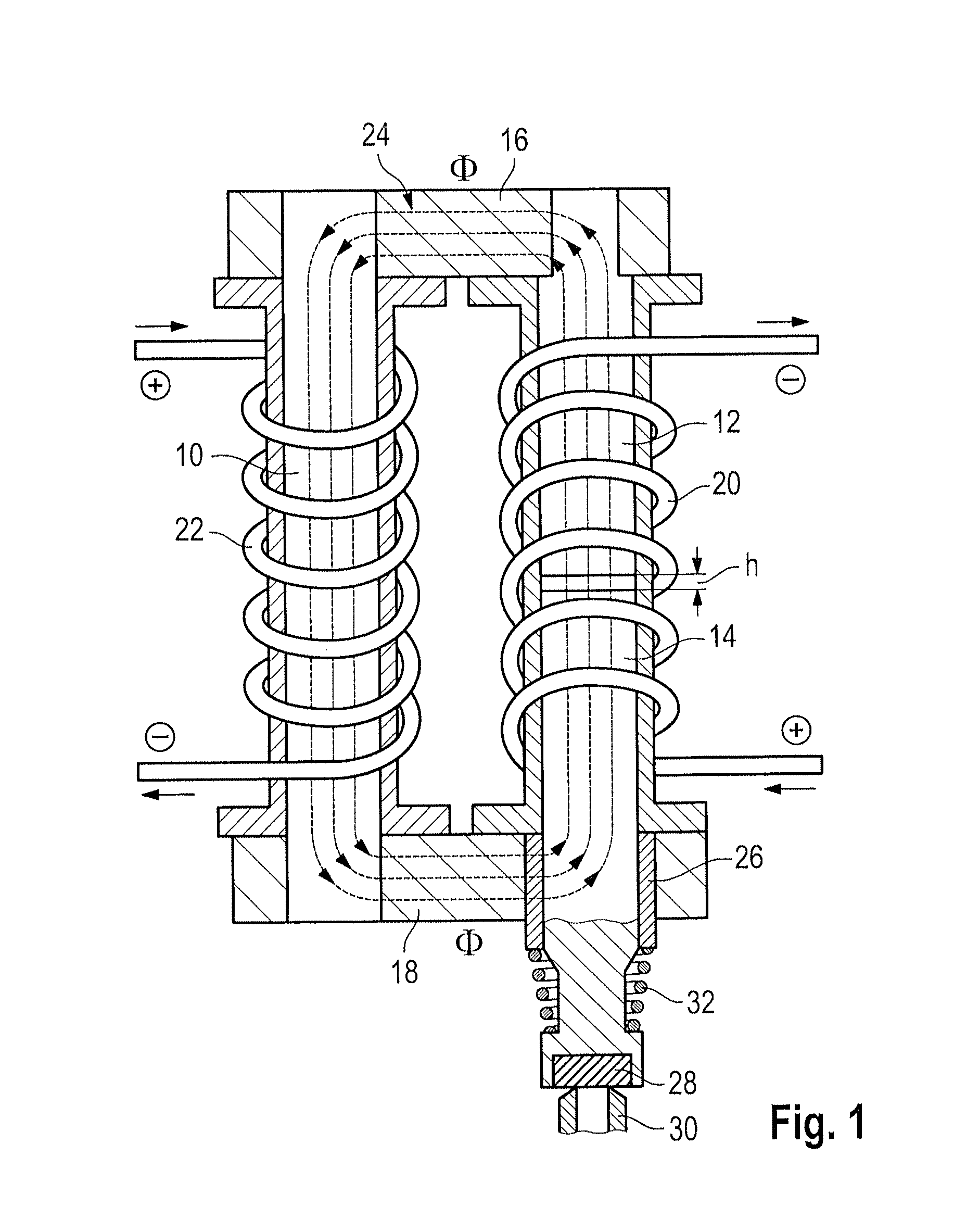
[0032]The lifting armature drive shown in FIG. 1 consists of a magnetic yoke and two solenoid coils. The magnetic yoke is made up of a yoke rod 10, a yoke stud 12, a core plug 14, and two yoke legs 16, 18. The magnetic yoke constitutes a ferromagnetic circuit which is only interrupted by an air gap of a height h between the yoke stud 12 and the core plug 14. A first solenoid coil 20 surrounds the yoke stud 12 and the core plug 14. A second solenoid coil 22 surrounds the yoke rod 10. The solenoid coils 20, 22 may be operated in parallel or in a series connection. With the polarities as specified in FIG. 1, a flux direction of the magnetic flux Φ is obtained as indicated by arrows 24.

[0033]The core plug 14 is guided for axial movement and passes through a pole sleeve 26 inserted in an opening of the yoke leg 18. The free face end of the core plug 14 carries a sealing body 28 which cooperates with a sealing seat 30 of a valve that is indicated only by this sealing seat 30 in FIG. 1. A ...


PUM


Abstract

An electromagnetic drive with a lifting armature is disclosed, in particular for a valve, which, while having small dimensions, is suitable to achieve high magnetic forces and the components of which can be freely combined with one another in a large variety of ways. This allows an adaptation to a specified structural space without specific components having to be fabricated. The same standardized components are just combined with each other differently. The drive includes a magnetic yoke with two parallel spaced yoke legs, a yoke rod extending perpendicular to and connecting the yoke legs, a yoke stud extending parallel to the yoke rod and spaced from the yoke rod, and a core plug extending coaxially with the yoke stud. The core plug is axially movable and passes through one of the yoke legs. The core plug further defines an air gap with the yoke stud.

Description

RELATED APPLICATION[0001]This application claims priority to German application 20 2008 015 303.4, which was filed Nov. 19, 2008.FIELD OF THE INVENTION[0002]The present invention relates to an electromagnetic drive with a lifting armature, in particular for a valve.BACKGROUND OF THE INVENTION[0003]Lifting armature drives are widely used in valves and relays. They are particularly suitable for miniaturized designs. The essential components of a lifting armature drive include a magnetic yoke that constitutes a ferromagnetic circuit and a solenoid coil that surrounds one of the yoke legs. The other yoke leg is divided into a fixed component of the magnetic yoke and a movable rod which constitutes the actuating member of the drive.SUMMARY OF THE INVENTION[0004]The invention provides an electromagnetic drive with a lifting armature, in particular for a valve, which, while having small dimensions, is suitable to achieve high magnetic forces and the components of which can be freely combin...

Claims


Application Information

Patent Timeline
Patent Type & Authority Applications(United States)
IPC IPC(8): F16K31/02
CPCH01F7/081F16K31/0641
Inventor BEYER, OLAFDOERR, MARTINGAUSS, WILLHEIMHETTINGER, MARTINKAHL, SEBASTIAN
Owner BURKERT WERKE
Learn More