
Method for power consumption in wireless sensor network

a wireless sensor and wireless sensor technology, applied in the field of wireless sensor networks, can solve the problems of difficult or impossible replacement of the exhausted battery of the node with a new battery, the most energy-consuming operation of transmitting/receiving packets, and the difficulty of managing the operator, so as to reduce unnecessary power consumption, reduce power consumption in the wireless sensor network, and reduce the effect of unnecessary power consumption

Inactive Publication Date: 2010-05-20
SAMSUNG ELECTRONICS CO LTD
View PDF2 Cites 31 Cited by
  • Summary
  • Abstract
  • Description
  • Claims
  • Application Information

AI Technical Summary

Benefits of technology

[0013]The present invention has been made to address at least the above problems and / or disadvantages and to provide at least the advantages described below. Accordingly, an aspect of the present invention provides a method for reducing power consumption in a wireless sensor network.
[0014]Another aspect of the present invention provides a method for reducing unnecessary power consumption by using a Time Division Multiple Access (TDMA) scheme in a wireless sensor network.
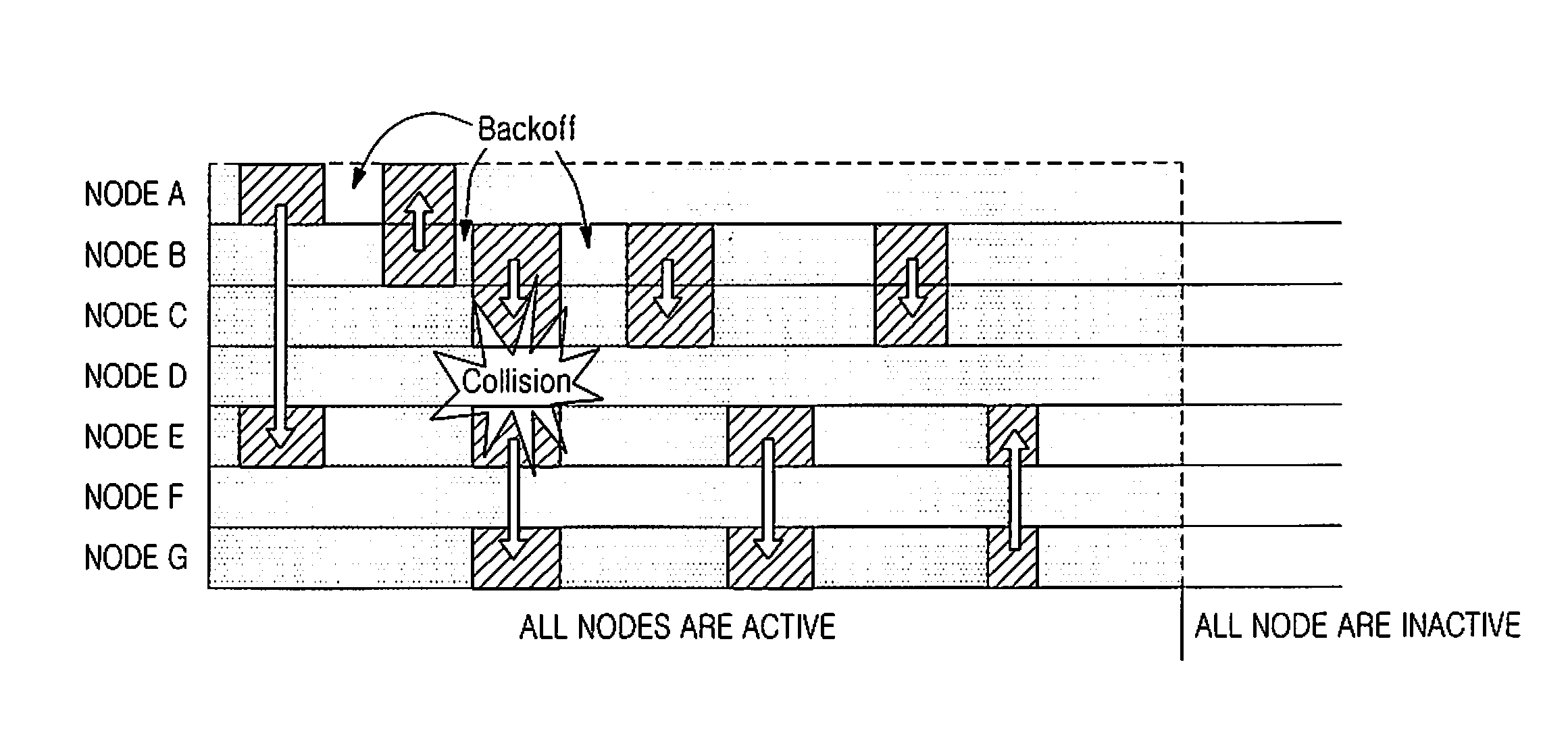
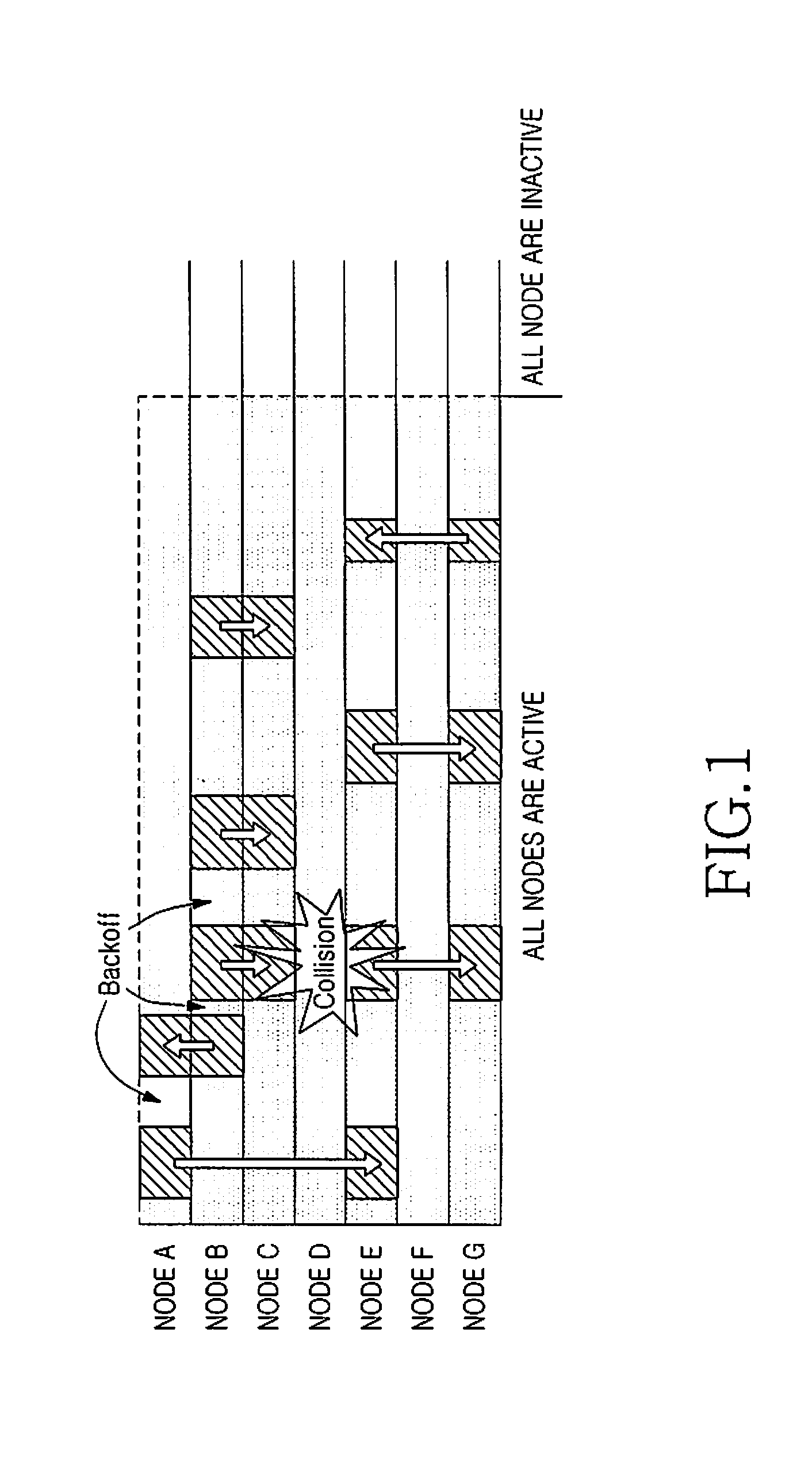
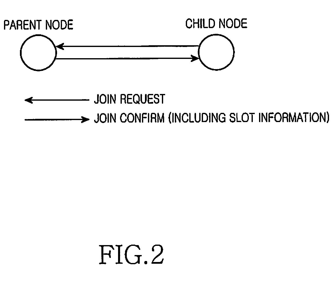
[0015]According to one aspect of the present invention, a method is provided for reducing power consumption in a wireless sensor network. A first node sets an optimized path destined for a sink node by using a common channel in which the first node and a second node use a Carrier Sense Multiple Access (CSMA) scheme. The first node sets a first channel for packet transmission / reception to / from child nodes of the first node, and allocates transmission / reception slots for packet transmission / reception to / from the respective child nodes of the first node in the first channel. The first node transmits a packet to the second node, which is allocated a first transmission slot among the transmission slots of the first channel, through the first transmission slot using a Time Division Multiple Access (TDMA) scheme. When a packet is not received from the second node, which is allocated a first reception slot among the reception slots of the first channel, through the first reception slot within a first set amount of time, the first node allows the first reception slot to transition to an inactive state. The first node is one of the sink node, at least one parent node connected to the sink node, and at least one child node connected to the at least one parent node. The second node is one of the child nodes of the first node.

Problems solved by technology

In general, a wireless sensor network is installed in an area that is difficult for an operator to manage, such as a comparatively large area, a building, and a structure.
However, if there is a node with an exhausted battery in the wireless sensor network, it is often difficult or impossible to replace the exhausted battery of the node with a new battery.
Therefore, while a transmitting node using the CSMA scheme can always transmit a packet without restrictions from other conditions when a channel is not used, a receiving node must always be placed in a reception standby state because it does not know when and from which node a transmitted packet will be received.
Among the various operations of a node in a wireless sensor network, the operation of transmitting / receiving a packet is one of the most energy-consuming operations.
Thus, even when the corresponding node is not in the process of packet transmission / reception, but is placed in a reception standby state, it consumes almost the same power as packet transmission / reception.
As a result, the power wasted due to the reception standby state increases as the number of nodes increases, or as the density of nodes existing in the same area increases.
However, even when the duty cycling scheme is applied to the typical wireless sensor network employing the CSMA scheme, there are limitations in reducing power wasted when each node is placed in a reception standby state.

Method used


Image

  • Method for power consumption in wireless sensor network
  • Method for power consumption in wireless sensor network
  • Method for power consumption in wireless sensor network

Examples


Embodiment Construction

[0027]Embodiments of the present invention are described in detail with reference to the accompanying drawings. The same or similar components may be designated by the same or similar reference numerals although they are illustrated in different drawings. Detailed descriptions of constructions or processes known in the art may be omitted to avoid obscuring the subject matter of the present invention.

[0028]The present invention provides a method for reducing power consumption in a wireless sensor network. Also, the present invention provides a method for reducing unnecessary power consumption by using a TDMA scheme in a wireless sensor network. In the following description, it is assumed that a wireless sensor network to which the present invention is applied includes fixed sensor nodes (hereinafter referred to as “nodes”) and one fixed sink node collecting sensing data from the nodes.

[0029]An operation of the present invention is largely divided into an “initial network setting proc...


PUM


Abstract

A method for reducing power consumption in a wireless sensor network is provided. An optimized path destined for a sink node is set using a common channel in which first and second nodes use a CSMA scheme. A first channel is set and transmission / reception slots for packet transmission / reception arc allocated in the first channel. A packet is transmitted to the second node through a first transmission slot using a TDMA scheme. When a packet is not received from the second node through a first reception slot within a first set amount of time, the first reception slot is allowed to transition to an inactive state. The first node is one of the sink node, at least one parent node, and at least one child node of the parent node, and the second node is one of child nodes of the first node.

Description

PRIORITY[0001]This application claims priority under 35 U.S.C. §119(a) to an application entitled “Method for Power Consumption in Wireless Sensor Network” filed in the Korean Intellectual Property Office on Nov. 20, 2008 and assigned Serial No. 10-2008-0115705, the content of which is incorporated herein by reference.BACKGROUND OF THE INVENTION[0002]1. Field of the Invention[0003]The present invention relates generally to wireless sensor networks, and more particularly, to a method for reducing power consumption in a wireless sensor network.[0004]2. Description of the Related Art[0005]In general, a wireless sensor network is installed in an area that is difficult for an operator to manage, such as a comparatively large area, a building, and a structure. The wireless sensor network operates by itself to collect, process, and report environmental information and situation information required by the operator. Therefore, nodes included in the wireless sensor network usually operate us...

Claims


Application Information

Patent Timeline
Patent Type & Authority Applications(United States)
IPC IPC(8): H04B7/212
CPCY02B60/50H04B7/2656Y02D30/70H04L12/28
Inventor IN, JEONG-SIKCHOI, HYO-HYUNKIM, EUI-JIK
Owner SAMSUNG ELECTRONICS CO LTD
Learn More