Automatic assembly jig
- Summary
- Abstract
- Description
- Claims
- Application Information
AI Technical Summary
Benefits of technology
Problems solved by technology
Method used
Image

Examples
Embodiment Construction
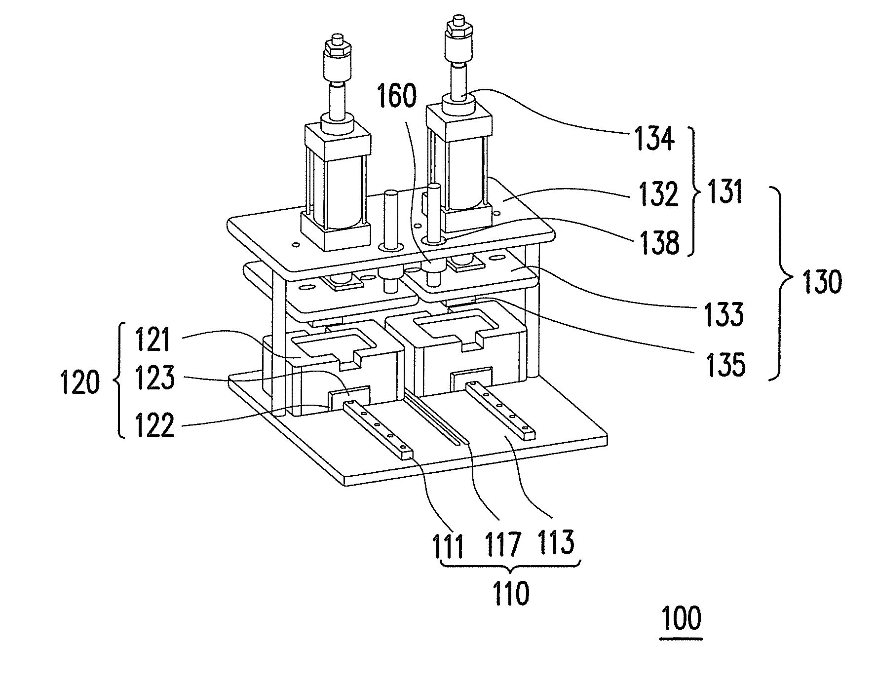
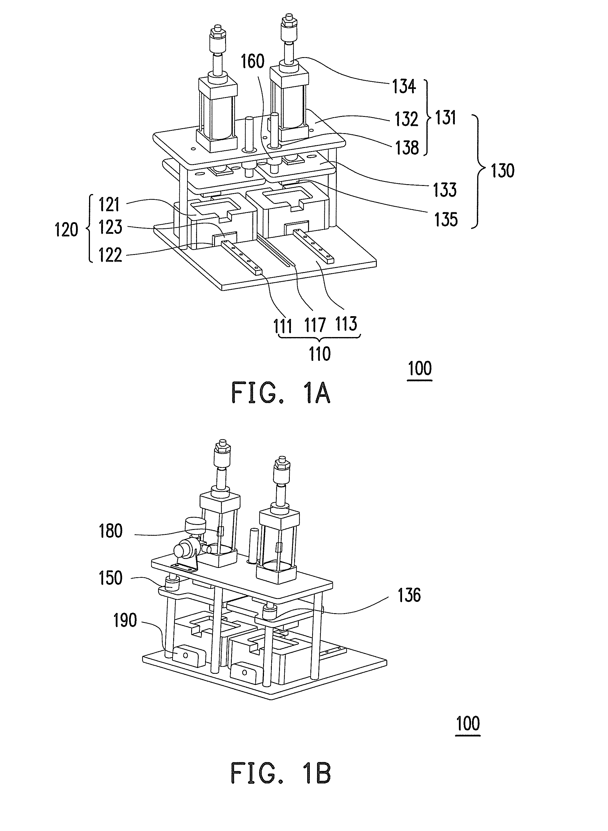
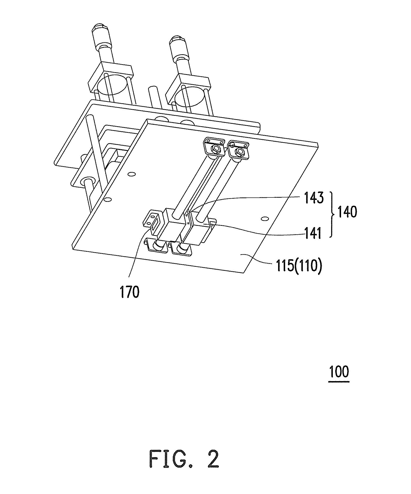
[0027]FIGS. 1A and 1B illustrate the structure of an automatic assembly jig according to one embodiment of the present invention, and FIG. 2 is a bottom view of the automatic assembly jig of FIGS. 1A and 1B. Referring to FIGS. 1A, 1B and 2, the automatic assembly jig 100 of the present embodiment includes a working platform 110, two carriers 120, two pressure exerting devices 130, and two gears 140. In this embodiment, the automatic assembly jig 100 includes two carriers 120, two pressure exerting devices 130 and two gears 140 for elaboration only but not for limiting the scope of the invention. That is, in another embodiment, the automatic assembly jig includes one carrier, one pressure exerting device and one gear. Or, in the other embodiment, the automatic assembly jig includes more than two carriers, more than two pressure exerting devices and more than two gears.
[0028]The pressure exerting devices 130 are disposed above the working platform 110. The working platform 110 has two...
PUM
| Property | Measurement | Unit |
|---|---|---|
| Time | aaaaa | aaaaa |
| Pressure | aaaaa | aaaaa |
Abstract
Description
Claims
Application Information
 - Generate Ideas
- Intellectual Property
- Life Sciences
- Materials
- Tech Scout
- Unparalleled Data Quality
- Higher Quality Content
- 60% Fewer Hallucinations
Browse by: Latest US Patents, China's latest patents, Technical Efficacy Thesaurus, Application Domain, Technology Topic, Popular Technical Reports.
© 2025 PatSnap. All rights reserved.Legal|Privacy policy|Modern Slavery Act Transparency Statement|Sitemap|About US| Contact US: help@patsnap.com