Check patentability & draft patents in minutes with Patsnap Eureka AI!

Microelectromechanical gyroscope with rotary driving motion and improved electrical properties

a micro-electromechanical and rotary driving technology, applied in the direction of acceleration measurement using interia forces, speed measurement using gyroscopic effects, devices using electric/magnetic means, etc., can solve the problems of not optimizing in the whole respect of manufacturing simplicity, size reduction, and efficiency in terms of electrical characteristics

Active Publication Date: 2010-05-27
STMICROELECTRONICS SRL
View PDF41 Cites 71 Cited by
  • Summary
  • Abstract
  • Description
  • Claims
  • Application Information

AI Technical Summary

Benefits of technology

[0028]One embodiment is a microelectromechanical (MEMS) gyroscope that is improved in regards to sensitivity to external stresses and robustness in regard to disturbance. The MEMS gyroscope includes a die, having a substrate and a frame, where the frame has a detection region and a first side extending along a first horizontal axis. The MEMS gyroscope also includes a driving mass, anchored to the substrate via elastic anchorage elements, set in the detection region, and designed to be rotated in a plane with a movement of actuation about a vertical axis, and a first pair and a second pair of first sensing masses, suspended inside, and coupled to, the driving mass via respective elastic supporting elements so as to be fixed with respect thereto in the movement of actuation and perform a detection movement of rotation out of the plane in response to a first angular velocity. The first sensing masses of the first pair and the first sensing masses of the second pair being aligned in respective directions, having non-zero inclinations of opposite sign with respect to the first horizontal axis.

Problems solved by technology

Even though the described gyroscope represents a considerable improvement over other gyroscopes of a known type, it is not altogether optimized in respect of manufacturing simplicity, size reduction, efficiency in terms of electrical characteristics, and immunity to disturbance.

Method used


Image

  • Microelectromechanical gyroscope with rotary driving motion and improved electrical properties
  • Microelectromechanical gyroscope with rotary driving motion and improved electrical properties
  • Microelectromechanical gyroscope with rotary driving motion and improved electrical properties

Examples


Embodiment Construction

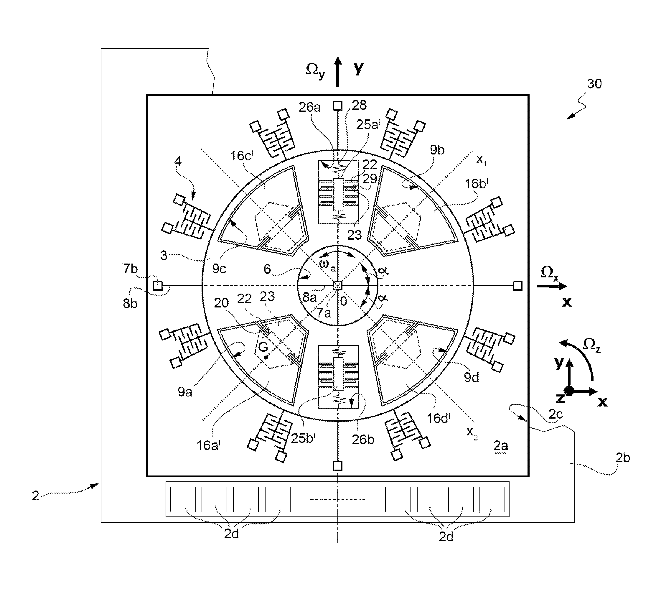
[0036]As will be described in detail hereinafter, an aspect of the present disclosure envisages providing a microelectromechanical gyroscope having an arrangement of the sensing masses such as to enable an increase in the sensitivity of the sensor and in general an improvement of its electrical characteristics.

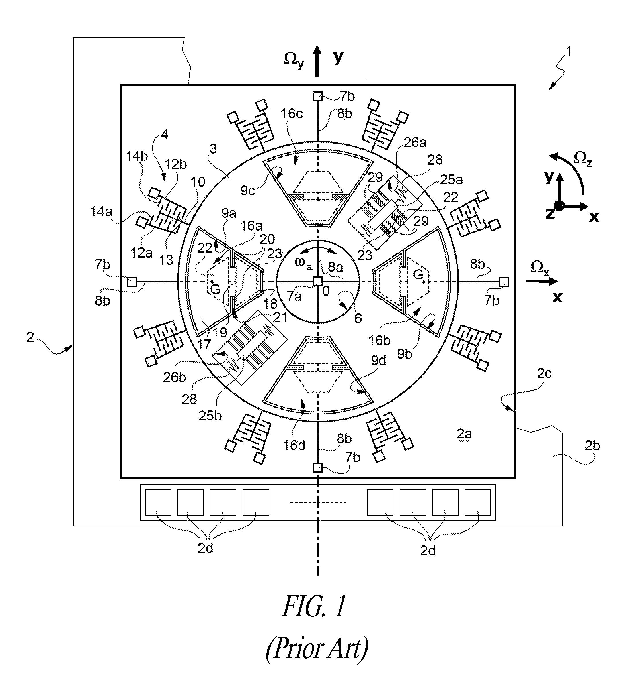
[0037]As is shown in FIG. 4, where the same reference numbers are used for indicating elements similar to others already described with reference to FIG. 1, the microelectromechanical gyroscope, here designated by 30, differs from the gyroscope 1 of FIG. 1 substantially on account of a different arrangement of the first sensing masses, here designated by 16a′-16d′, and of the second sensing masses, here designated by 25a′, 25b′.

[0038]In greater detail, the first sensing masses 16a′, 16b′ of the first pair are aligned in a first diametric direction x1, inclined with respect to the first horizontal axis x of the die 2 by an angle of inclination α (considered in a counterclockwi...


PUM

PropertyMeasurementUnit
Angleaaaaaaaaaa
Angleaaaaaaaaaa
Angular velocityaaaaaaaaaa

Abstract

An integrated microelectromechanical structure is provided with: a die, having a substrate and a frame, defining inside it a detection region and having a first side extending along a first axis; a driving mass, anchored to the substrate, set in the detection region, and designed to be rotated in a plane with a movement of actuation about a vertical axis; and a first pair and a second pair of first sensing masses, suspended inside the driving mass via elastic supporting elements so as to be fixed with respect thereto in the movement of actuation and so as to perform a detection movement of rotation out of the plane in response to a first angular velocity; wherein the first sensing masses of the first pair and the first sensing masses of the second pair are aligned in respective directions, having non-zero inclinations of opposite sign with respect to the first axis.

Description

BACKGROUND[0001]1. Technical Field[0002]The present disclosure relates to a microelectromechanical structure, in particular a biaxial or triaxial gyroscope, provided with a rotary driving movement and improved electrical characteristics, in particular in terms of sensitivity in the detection of angular velocities.[0003]2. Description of the Related Art[0004]As is known, micromachining techniques enable manufacturing of microelectromechanical structures or systems (MEMS) within layers of semiconductor material, which have been deposited (for example, a polycrystalline-silicon layer) or grown (for example, an epitaxial layer) on sacrificial layers, which are removed via chemical etching.[0005]Inertial sensors, accelerometers, and gyroscopes obtained with this technology are having an increasing success, for example, in the automotive field, in inertial navigation, or in the field of portable devices.[0006]In particular, known to the art are integrated gyroscopes made of semiconductor ...

Claims


Application Information

Patent Timeline
IPC IPC(8): G01C19/56H05K13/00
CPCG01C19/56G01C19/5712Y10T29/49002
Inventor CORONATO, LUCACAZZANIGA, GABRIELEZERBINI, SARAH
Owner STMICROELECTRONICS SRL
Features
  • R&D
  • Intellectual Property
  • Life Sciences
  • Materials
  • Tech Scout
  • Unparalleled Data Quality
  • Higher Quality Content
  • 60% Fewer Hallucinations
Learn More