Saw blade and method of manufacturing the same

a technology of saw blades and manufacturing methods, applied in the field of saw blades, can solve the problems of reducing productivity, reducing productivity, and reducing productivity, and achieve the effect of constant width, constant width, and substantial constant initial cutting width

Inactive Publication Date: 2010-05-27
CLOUTIER MICHAEL F
View PDF3 Cites 23 Cited by
  • Summary
  • Abstract
  • Description
  • Claims
  • Application Information

AI Technical Summary

Benefits of technology

[0007]At least one embodiment may be summarized as a saw blade including a plurality of protruding tip support regions spaced around the periphery of a substantially circular body, each tip support region having a substantially planar upper tooth face and a tip seat, and a plurality of cutting tips wherein each cutting tip is secured to the tip seat of each tip support region with a top face of each cutting tip substantially parallel to and offset from each respective upper tooth face. The tip support region may further include a grindable tip reinforcement portion configured to support each respective cutting tip on at least a portion of a back face thereof. The tip seat of each tip support region may further include a shoulder having a receiving angle less than 90 degrees to receive a portion of the cutting tip secured therein, and preferably a receiving angle of about 70 degrees. The top face of each cutting tip may be offset from each respective upper tooth face by at least 0.030 inches. Each cutting tip may be configured to maintain a cutting edge at a substantially constant width when material is removed from the top face of each cutting tip. Each cutting tip may be configured to maintain a cutting edge within 0.003 inches of an initial cutting width when material is removed from the top face of the cutting tip from an initial top clearance to a condition when the upper tooth face proximate the cutting tip is substantially coplanar with the top face. Each of the cutting tips may be configured to have an initial tangential angle of about 2 degrees and an initial radial angle of about 1.5 degrees. For each cutting tip, a ratio of a length of the cutting tip to the initial distance between the top face of the cutting tip and the upper tooth face of the tip support region proximate thereto may be less than 17:1, and preferably less than 12:1. For each cutting tip, a ratio of a thickness of the cutting tip to the initial distance between the top face of the cutting tip and the upper tooth face of the tip support region proximate thereto may be less than 4:1, and preferably less than 3:1. A front face of each cutting tip may be coated with a hardening agent. The hardening agent may be titanium aluminum nitride.
[0008]At least one embodiment may be summarized as a saw blade including a plurality of protruding tip support regions spaced around the periphery of a substantially circular body, each tip support region having a grindable tip reinforcement portion and a tip seat, and a plurality of cutting tips, each cutting tip secured to the tip seat of each tip support region, and wherein the grindable tip reinforcement portion of each tip support region is configured to support each respective cutting tip on at least a portion of a back face thereof. The tip seat of each tip support region may include a shoulder having a receiving angle less than 90 degrees to receive a portion of the cutting tip secured therein. Each tip support region may further include a substantially planar upper tooth face wherein a top face of each cutting tip is substantially parallel to and offset from each respective upper tooth face. The top face of each cutting tip may be offset from each respective upper tooth face by at least 0.030 inches. Each cutting tip may be configured to maintain a cutting edge at a substantially constant width when material is removed from the top face of each cutting tip. At least one embodiment may be summarized as a cutting tip having a unitary tip body, the tip body including: a front face having a hardening agent applied thereto; a top face contiguous with the front face at a cutting edge, the cutting edge having an initial cutting width; and a first side face and a second side face located on opposite sides of the tip body and contiguous with both the front face and the top face, each of the first side face and the second side face characterized by a radial angle and a tangential angle, the radial angle and tangential angle configured to maintain the initial cutting width substantially constant throughout a usable depth of the cutting tip. The cutting tip may have a usable depth of at least 0.030 inches. The cutting tip may have an initial tangential angle of about 2 degrees and an initial radial angle of about 1.5 degrees. The difference between the initial cutting width and a width across the front face throughout the usable depth may be less than or equal to 0.003 inches. A ratio of a length of the cutting tip to the usable depth of the cutting tip may be less than 17:1, and preferably less than 12:1. A ratio of a thickness of the cutting tip to the usable depth of the cutting tip may be less than 4:1, and preferably less than 3:1. The unitary tip body of the cutting tip may further include a back face contiguous with the top face and both the first side face and the second side face, and a bottom face located opposite the front face, wherein a lower tip angle between the back face and the bottom face of the tip body is less than 90 degrees, and preferably about 70 degrees.

Problems solved by technology

The use of saw blades with conventional hardened cutting tips, however, require periodic maintenance and / or replacement of the cutting tips that can lead to reduced productivity.
Under such conditions, the cutting tips of a saw blade are frequently worn and / or damaged, thus requiring periodic re-sharpening and / or replacement.
The need to re-sharpen or replace cutting tips necessitates shutting down a saw for a period of time and leads to diminished productivity.

Method used


Image

  • Saw blade and method of manufacturing the same
  • Saw blade and method of manufacturing the same
  • Saw blade and method of manufacturing the same

Examples


Embodiment Construction

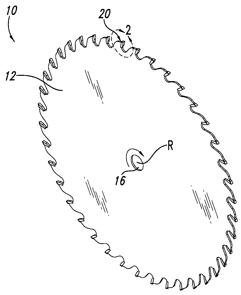
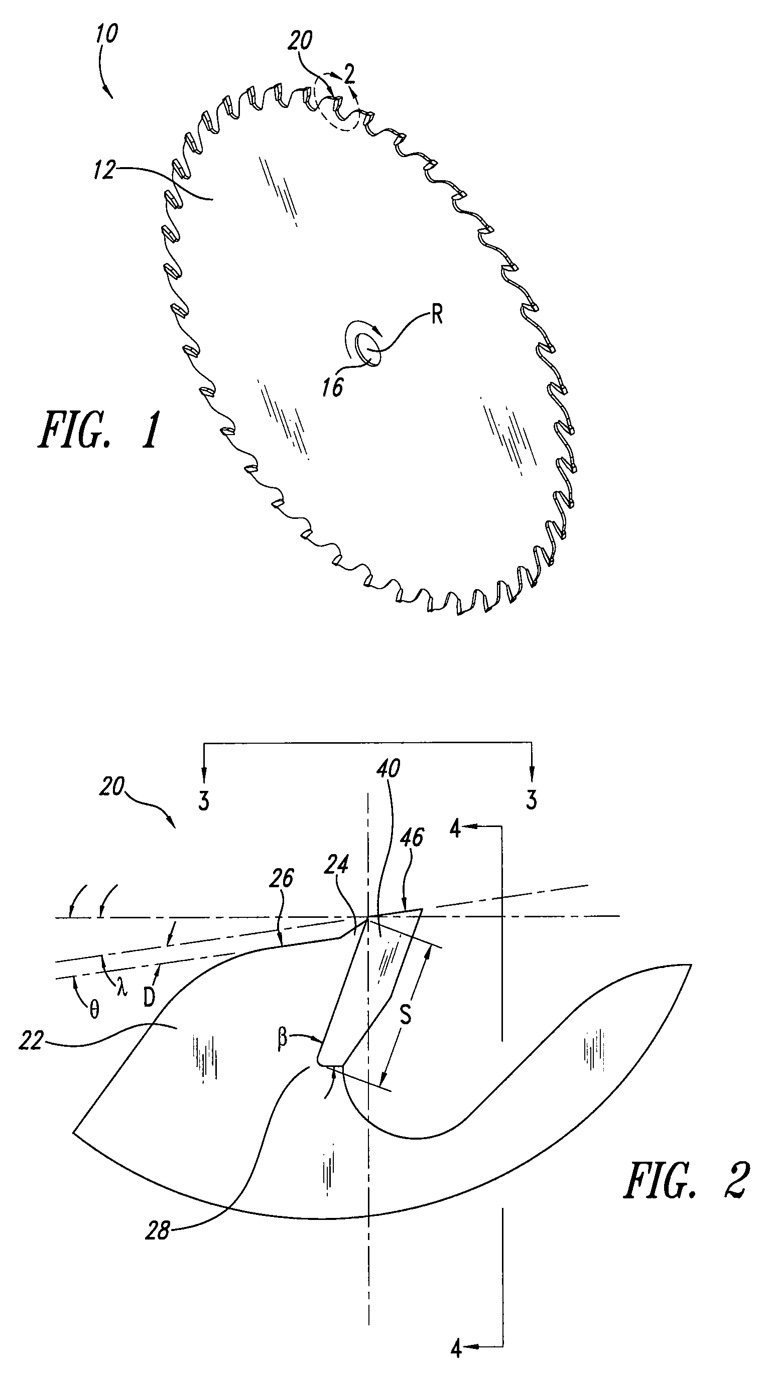
[0016]FIGS. 1 through 5 illustrate one embodiment of a circular saw blade 10 having enhanced wear and performance characteristics particularly suitable for use in the lumber industry. As shown in FIG. 1, the saw blade 10 includes a plurality of teeth 20 spaced about the periphery of a substantially circular body 12. The blade 10 further includes a central aperture 16 for mounting the blade 10 on the arbor of a conventional circular saw. The teeth 20 of the saw blade 10 are spaced about the periphery of the blade body 12 with gullets located therebetween to assist in chip removal. In operation, the blade 10 rotates about a center of rotation R in the direction indicated in FIG. 1.

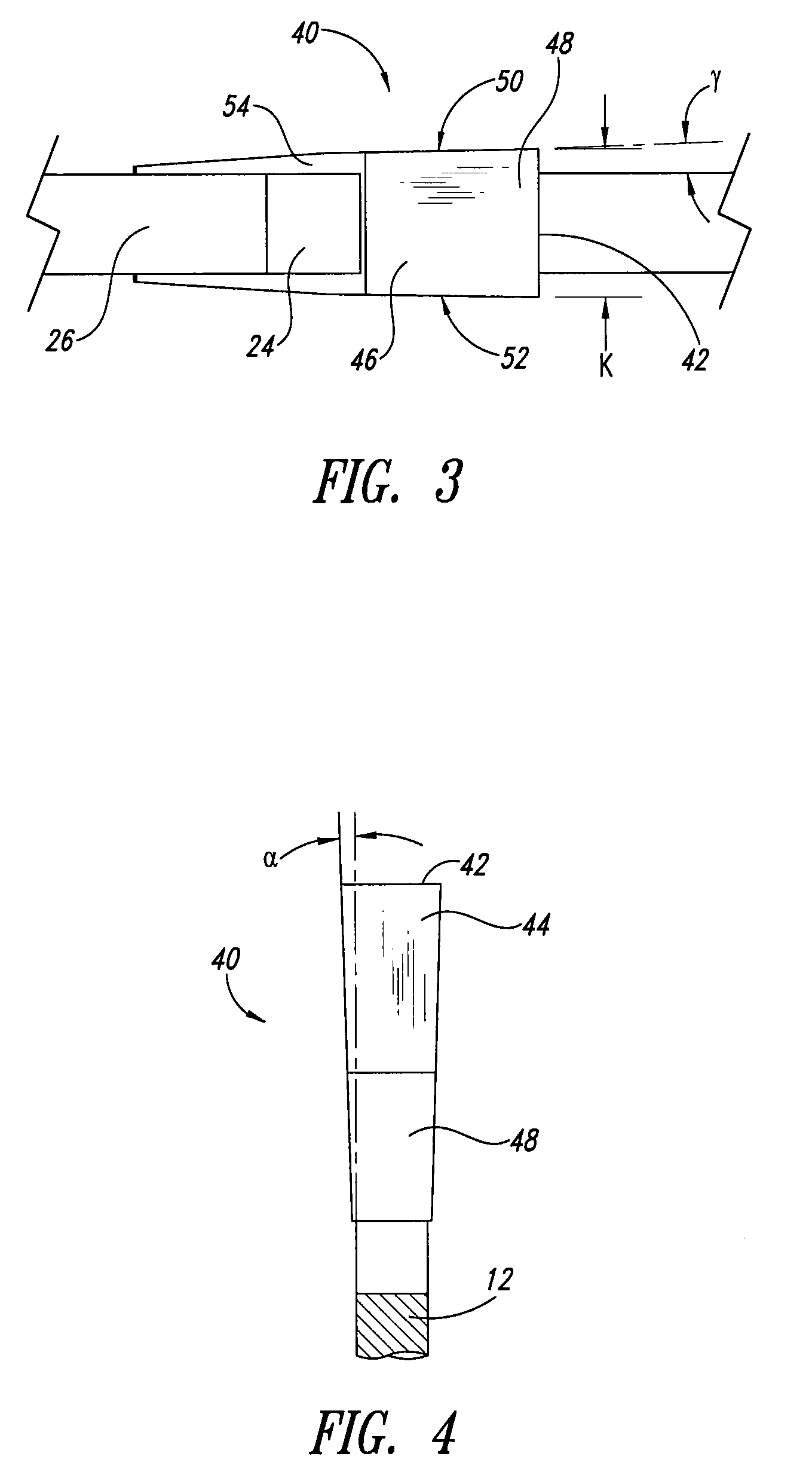
[0017]With reference to FIG. 2, each tooth 20 includes a cutting tip 40 secured to a tip support region 22. The tip support region 22 includes a tip seat 28 for receiving the cutting tip 40 and providing structural support thereto. The cutting tips 40 are preferably made of a hardened material, for example, ...


PUM

PropertyMeasurementUnit
receiving angleaaaaaaaaaa
widthaaaaaaaaaa

Abstract

A circular saw blade includes a substantially circular body having a plurality of protruding tip support regions spaced around the periphery thereof, each tip support region including at least a seat for supporting a cutting tip. The tip support region may further include a substantially planar upper tooth face, a grindable tip reinforcement portion and/or a lower tip angle less than 90 degrees. A cutting tip is secured to the seat of each tip support region preferably with a top face of each cutting tip substantially parallel to and offset from an upper tooth face of each tip support region. Each cutting tip of the circular saw blade is further configured to maintain a cutting edge at a substantially constant width when material is removed from the top face thereof. A method of manufacturing a saw blade is also provided.

Description

BACKGROUND[0001]1. Technical Field[0002]This disclosure is generally related to saw blades and methods of manufacturing the same, and more particularly to circular saw blades having hardened cutting tips and methods of manufacturing the same.[0003]2. Description of the Related Art[0004]Circular saw blades having hardened cutting tips, such as carbide tips, have been in use for many years and provide significant advantages over hardened steel blades. For example, the use of hardened cutting tips enable saw blades to operate at relatively higher cutting speeds while retaining the sharpness of a cutting edge for a relatively longer period of time. The use of saw blades with conventional hardened cutting tips, however, require periodic maintenance and / or replacement of the cutting tips that can lead to reduced productivity.[0005]Circular saw blades having hardened tips are used, for example, in the lumber industry in sawmills for the production of dimensional lumber—the saw blades being...

Claims


Application Information

Patent Timeline
Patent Type & Authority Applications(United States)
IPC IPC(8): B27B33/02B23D63/00
CPCB23D61/04B23D65/00B23D63/00Y10T83/936Y10T83/9319
Inventor CLOUTIER, MICHAEL F.
Owner CLOUTIER MICHAEL F
Why Eureka
Try Eureka