
Leg lift device and associated method

Inactive Publication Date: 2010-05-27
CASTELLANO BRADLEY
View PDF11 Cites 5 Cited by
  • Summary
  • Abstract
  • Description
  • Claims
  • Application Information

AI Technical Summary

Benefits of technology

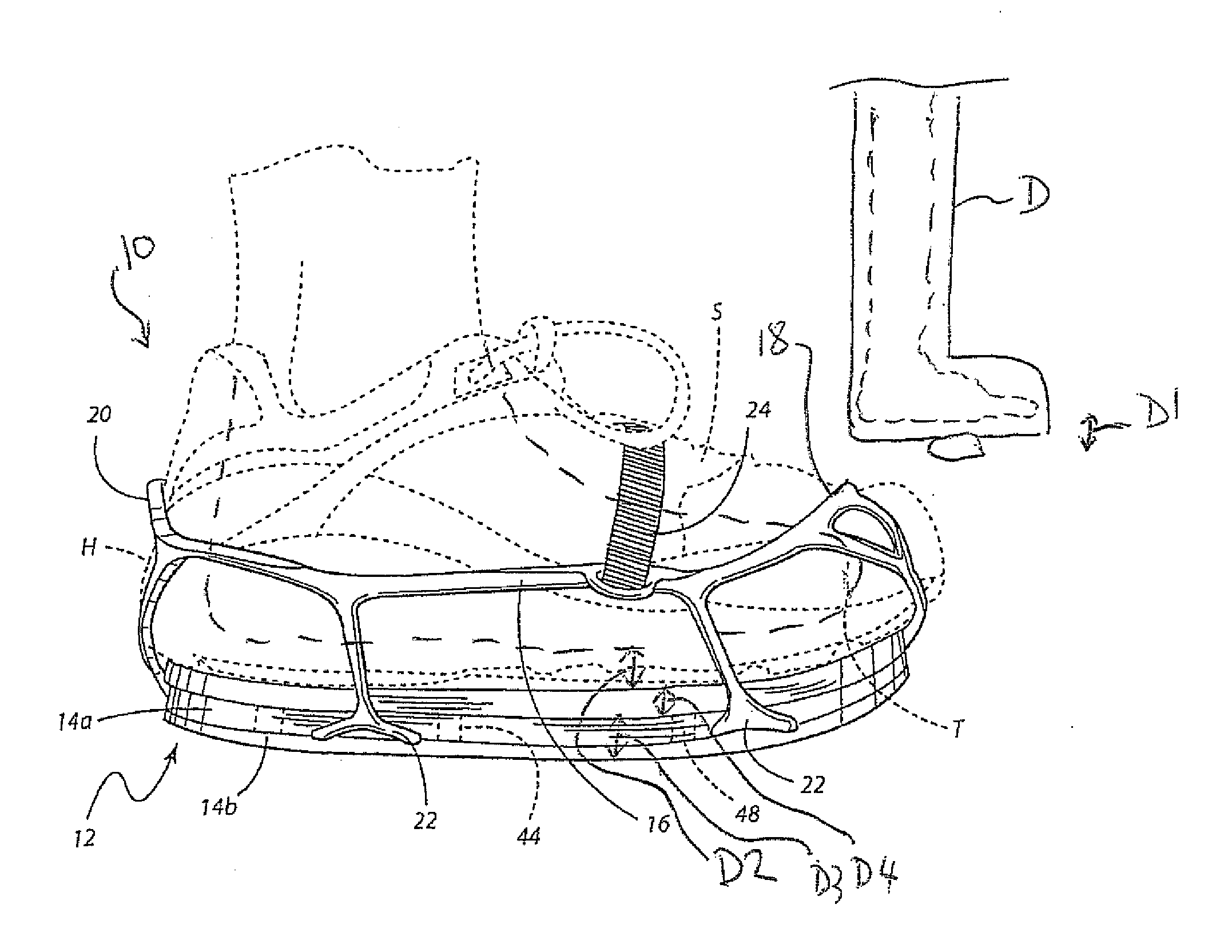
[0014]and reducing the physiological strain placed on the knees, hip and back of the patient when walking by arranging the therapeutic device and the leg lift device such that the first distance is substantially equal to the sum of the second distance, the first lift distance and the second lift distance.
[0024]Preferably the location of the recessed front edge is such that it allows decreased weight bearing pressure on the ball of foot while placing more contact on the mid foot and heel areas.
[0028]Preferably the location of the recessed rear edge is such that it allows decreased weight bearing pressure on the heel of the foot while placing more contact on the mid foot and ball.
[0029]According to a second aspect of the invention there is provided a method of reducing physiological strain on a patient comprising:
[0046]In accordance with an additional aspect of the present invention, a method is provided for reducing the physiological strain on an individual associated with walking when a fracture walker, cast boot or thick soled wound healing shoe is worn on a first foot by an individual. The method may be broadly described as comprising detachably connecting a leg lift device to a shoe worn on the second foot of an individual. The method may be further described as including the step of adjusting a height of a leg lift device worn on the second foot to substantially match the height of the fracture walker, cast boot or wound healing shoe worn on the first foot. This is done by selecting a lift insert of desired height or thickness from a series of lift inserts of differing heights and securing the selected lift insert to the sole of the leg lift device.
[0047]Still further, the method may be described as including the step of inserting a shoe to be worn on the second foot into the leg lift device and attaching the leg lift device to the shoe. Further, the method may include removing the shoe from the leg lift device as desired. Still further, the method may include inserting a different shoe into the leg lift device and attaching the leg lift device to the different shoe. The device may be adjusted to compensate for any difference in sole height between the first and second shoes by changing the lift insert used in the device. In this way, it is possible for the user to increase the height of any number of shoes owned by the user to substantially match the height of the fracture walker, cast boot or thick soled wound healing shoe so as to allow the user to walk in a level attitude using many different shoes owned by the individual and appropriate for wear at a particular occasion.

Problems solved by technology

A frequent complaint of patients that are utilizing this device is that it causes a marked inequality of limb length resulting in pain or injury to other areas of the body.
Knee, hip and even back pain are frequently an untoward effect of these walker boots.
A similar problem arises in patients or individuals walking in a cast boot or a thick soled wound healing shoe.
The added height of the cast boot or wound healing shoe worn on the foot of an individual's injured limb compared to a standard shoe worn on the foot of an individual's uninjured limb creates an unlevel condition that produces stress upon various body joints and the back.
Inside shoe devices, such as heel lifts, are less physiological in function and often do not provide adequate lift to completely compensate for the induced limb length discrepancy.
Accordingly, such devices are not true solutions for the problem.

Method used


Image

  • Leg lift device and associated method
  • Leg lift device and associated method
  • Leg lift device and associated method

Examples


Embodiment Construction

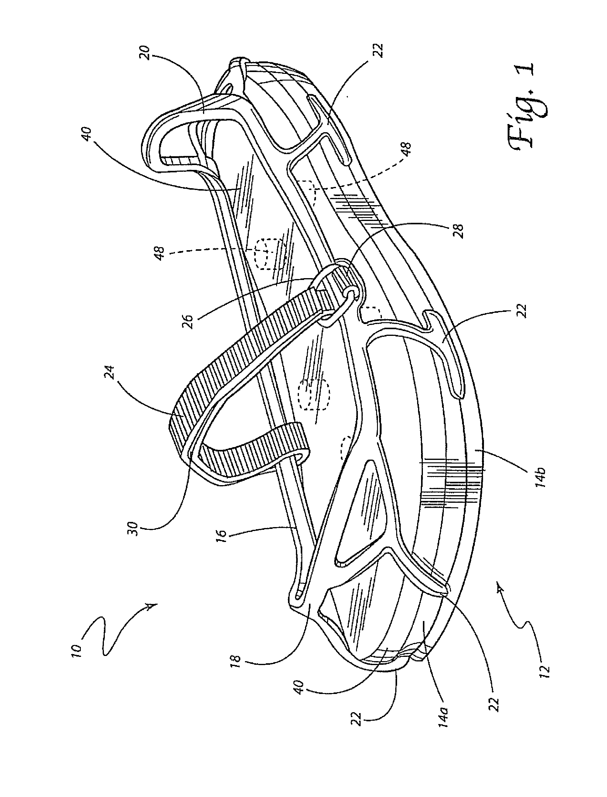
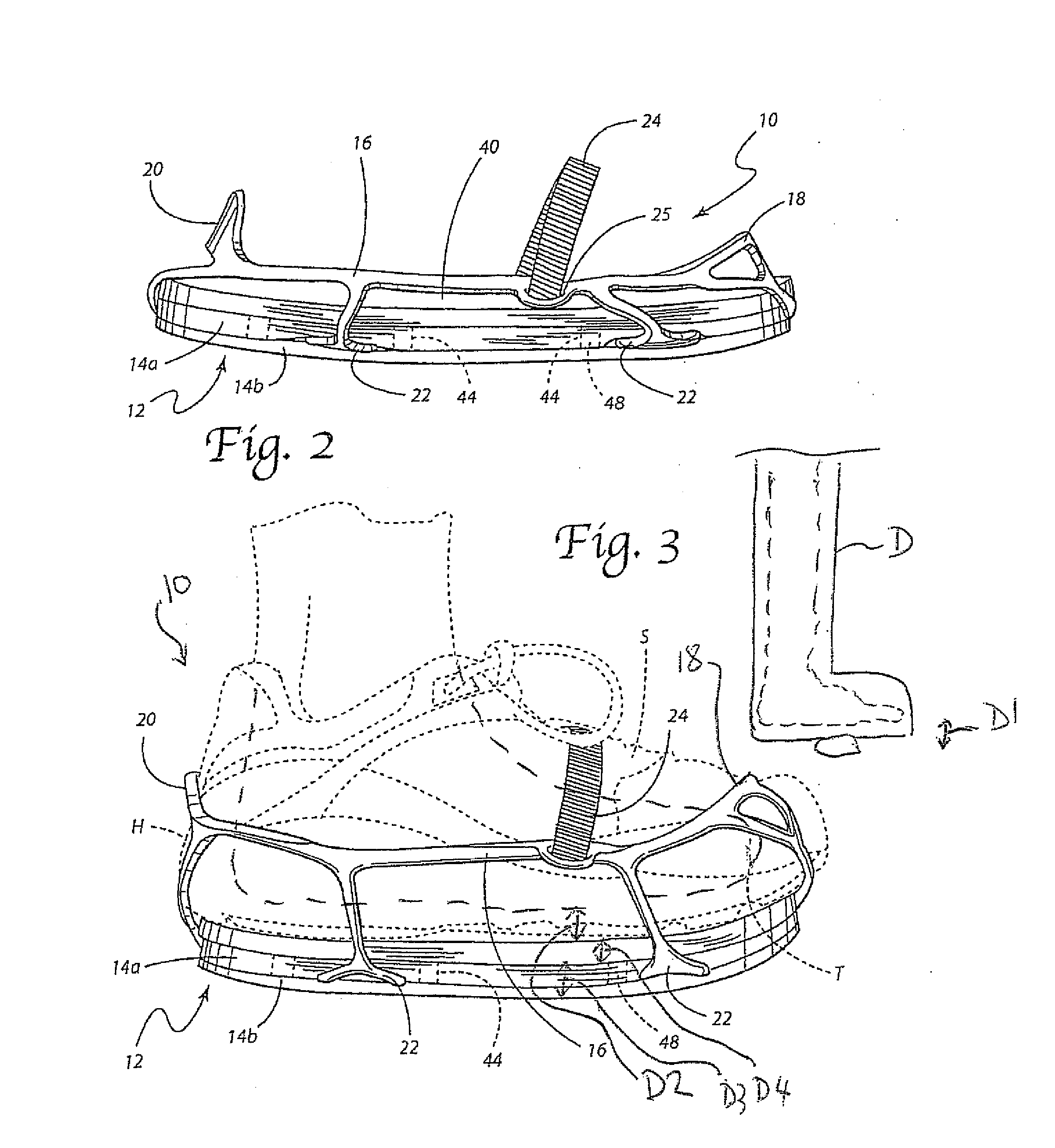
[0059]Reference is now made to FIGS. 1 and 2 illustrating the leg lift device 10 of the present invention. The leg lift device 10 comprises a sole 12, including first and second sections 14a, 14b, and a shoe receiver 16. The shoe receiver 16 may take the form of a mesh or web and includes a first section 18 to engage a toe of a shoe and a second section 20 to engage a heel of a shoe (see also FIG. 3). Typically the sole 12, including both sections 14a, 14b is made from a material selected from a group consisting of ethylene vinyl acetate (EVA), polyphenylene ether (PPE) rubber and polymeric foam materials. The shoe receiver 16 is made from an elastomeric material. Such a material may be selected from a group consisting of thermoplastic elastomer (TPE), rubber, latex or other synthetic elastomeric material suitable for the intended purpose.

[0060]As illustrated, the shoe receiver 16 includes a series of lugs 22 that are secured to the sole 12 at spaced points between the sole sections...


PUM


Abstract

A leg lift device is provided for attachment to a shoe and includes a sole, a lift insert and a shoe receiver attached to the sole. The shoe receiver includes a first section to engage a toe of a shoe and a second section to engage a heel of a shoe. The device also includes an attachment strap. A selected method is also provided. The device is used to reduce the physiological strain placed on the knees, hip and back of the patient when walking by arranging the therapeutic device and the leg lift device by arranging the height of the device and show to match that of a therapeutic device on the opposite foot. Also, the lift insert can include a transverse edge at either the front or rear which recessed from a corresponding edge of the sole plate to reduce pressure on the foot in these areas.

Description

[0001]This application is a continuation-in-part application from application Ser. No. 12 / 120,430, filed May 1.[0002]This application claims the benefit of U.S. Provisional Patent Application Ser. No. 60 / 974,798, filed on Sep. 24, 2007.TECHNICAL FIELD OF THE INVENTION[0003]The present invention relates generally to the physical rehabilitation field and, more particularly, to a leg lift device and associated method for reducing the physiological strain placed on the knees, hip and back when walking with a fracture walker, cast boot, thick soled wound healing shoe or the like.BACKGROUND OF THE INVENTION[0004]The recent use of fracture orthotic walkers has been a very common therapy modality for multiple types of lower leg and foot injuries. A frequent complaint of patients that are utilizing this device is that it causes a marked inequality of limb length resulting in pain or injury to other areas of the body. Knee, hip and even back pain are frequently an untoward effect of these wal...

Claims


Application Information

Patent Timeline
IPC IPC(8): A61G99/00A43B23/00A43B7/16
CPCA43B3/108A43B7/38A43B3/163
Inventor CASTELLANO, BRADLEY
Owner CASTELLANO BRADLEY
Learn More