Flexible, Electrically Heatable Hose

a flexible, electrically heatable technology, applied in the direction of service pipe systems, pipe heating/cooling, electric/magnetic/electromagnetic heating, etc., can solve the problem that the thermal insulation material cannot physically completely prevent heat loss, restricts the mobility of the hose system, and the live electrical conductors are at risk of losing their electrical contact with the heating element locally

Inactive Publication Date: 2010-05-27
MASTERFLEX SE
View PDF2 Cites 53 Cited by
  • Summary
  • Abstract
  • Description
  • Claims
  • Application Information

AI Technical Summary

Benefits of technology

[0015]The object of the present invention is therefore to provide a flexible, electrically heatable hose in which uniform heating over the hose length is ensured even in the event of major deformation of the hose.

Problems solved by technology

Thermal insulating materials cannot physically completely prevent the heat loss originating from a heated surface, but can only reduce it.
However, excessive layer thickness of the insulating material considerably restricts the mobility of a hose system.
However, the hose systems which are known from the prior art have the problem that there is a very major risk of the live electrical conductors losing their electrical contact with the heating element locally when the flexible hose being subjected to very severe and frequent tensile, bending and torsion loads.
Furthermore, corrosion can occur on the conductor surface in those conductor sections in which the contact between the electrical conductor and the heating element or the inner hose has been lost by severe and frequent tensile, bending and torsion loads.
This corrosion, which results in a greater contact resistance between the live conductor and the heating element, reduces the heat produced in the corresponding area of the inner hose and can thus in some cases result in points with less heating or even no heating.
In the event of severe and major deformation, the previously known hoses therefore cannot guarantee uniform heating over the entire hose length.
This pitch angle results in an optimum compromise between flexibility and robustness.

Method used


Image

  • Flexible, Electrically Heatable Hose
  • Flexible, Electrically Heatable Hose
  • Flexible, Electrically Heatable Hose

Examples


Embodiment Construction

[0084]The present invention is susceptible of embodiment in many different forms. While the drawings illustrate, and the specification describes, certain preferred embodiments of the invention, it is to be understood that such disclosure is by way of example only. There is no intent to limit the principles of the present invention to the particular disclosed embodiments.

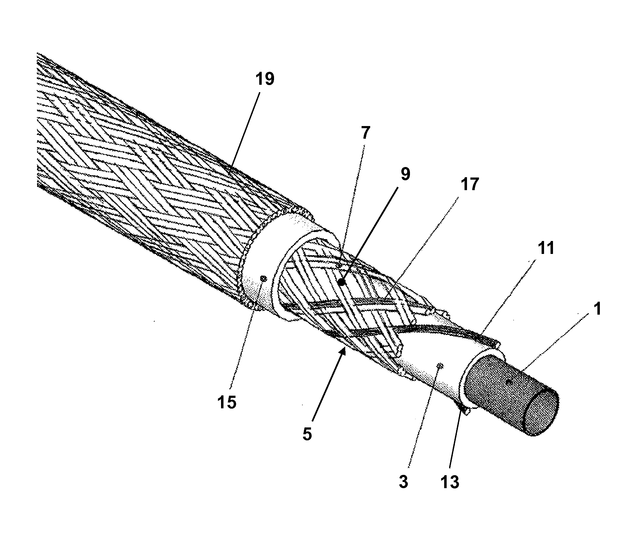
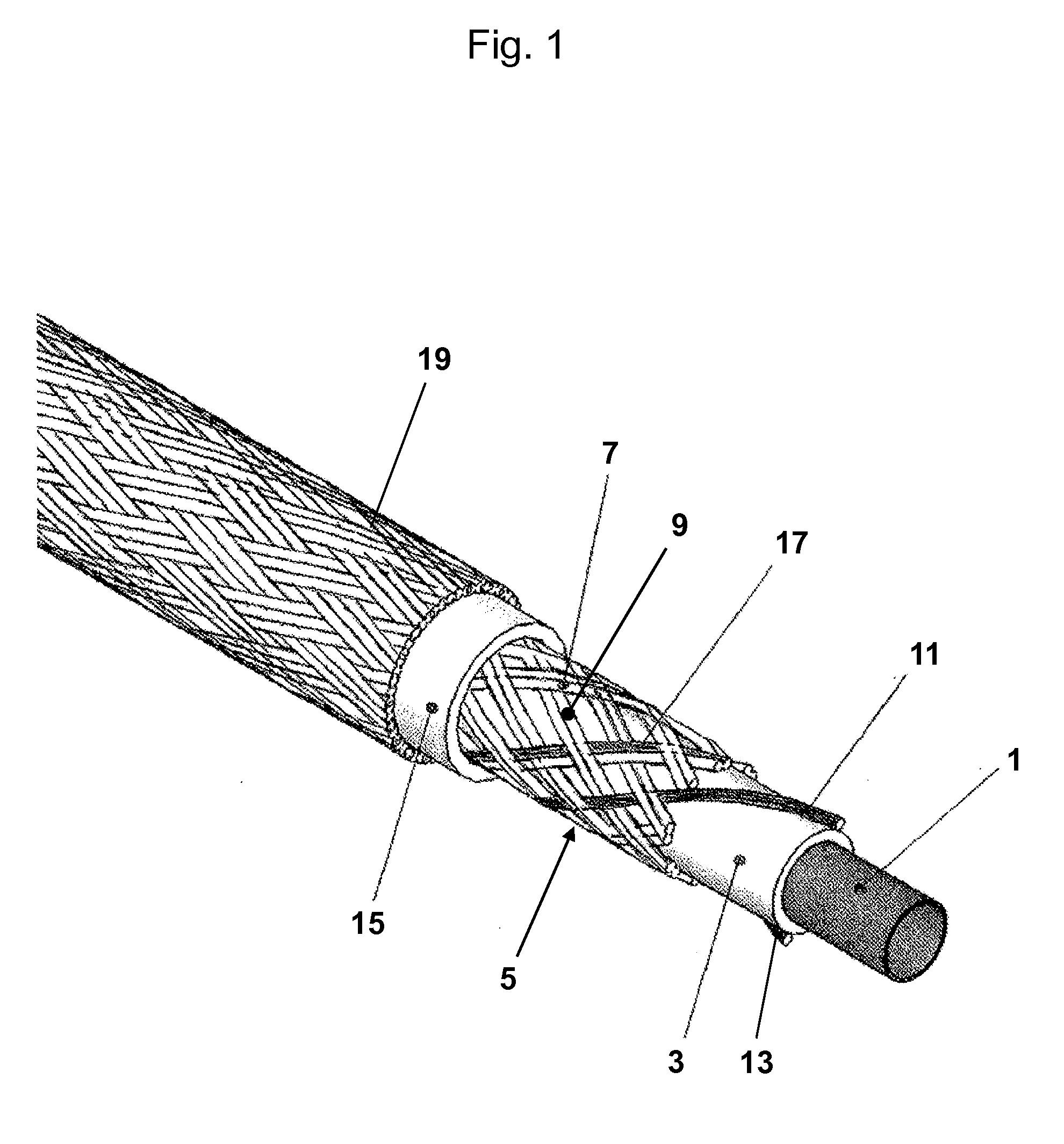
[0085]FIG. 1 shows one advantageous embodiment of a flexible, electrically heatable hose according to the invention which has an inner hose 1, where the inner hose 1 is intended to contain a medium which can flow, and to carry this medium in the direction in which the hose extends. A thermally conductive hose layer 3 is arranged around the inner hose 1. A braid 5 extends on this hose layer 3 and is wound in a helical shape around the hose layer 3 in the hose direction in the form of first strands 7 and second strands 9. The first strands 7 of the braid 5 extend in an anticlockwise helical shape in the direction of th...


PUM


Abstract

A flexible, electrically heatable hose having an elongated electrical conductor which extends in the helical shape in the hose direction is illustrated and described. The object of providing a flexible, electrically heatable hose in which uniform heating over the hose length is ensured even in the event of major deformation of the hose, is achieved by a hose which has an elongated electrical conductor which extends in a helical shape in the hose direction, wherein the electrical conductor is embedded in a braid. In this case, the braid has first and second strands, wherein the first strands extend in a helical shape in the hose direction in the same winding direction as the electrical conductor, and the second strands extend in a helical shape in the hose direction in the opposite winding direction to the electrical conductor. The pitch angle of the electrical conductor, which extends in a helical shape in the hose direction, of the first strands and of the second strands is in this case between 50° and 80°.

Description

CROSS-REFERENCE TO RELATED APPLICATION[0001]The present application claims the benefit of and priority from German Patent Application Serial No. DE 10 2008 055 891.5, filed Nov. 5, 2008, the entire disclosure of which is hereby incorporated by reference herein.BACKGROUND OF THE INVENTION[0002]1. Field of the Invention[0003]The present invention relates to a flexible, electrically heatable hose having an elongated electrical conductor, which extends in the helical shape in the hose direction.[0004]2. Discussion of the Prior Art[0005]In a multiplicity of processes for production or conveying of products, flow metering of liquid or gaseous substances, transport of gases or liquids or of products in the form of dust, and for conveying of heat carriers for heat treatment of substances through flexible hoses, it is necessary to supply an amount of heat externally, in order to maintain the temperature of the substances or even to increase the temperature of the substances.[0006]In this cas...

Claims


Application Information

Patent Timeline
Patent Type & Authority Applications(United States)
IPC IPC(8): H05B6/10F16L11/00E03B7/10F16L53/37F16L53/38
CPCF16L53/008F16L11/10F16L11/085F16L53/38F16L53/37
Inventor GUNZING, HANS-JURGENOSTERHOLT, GERD
Owner MASTERFLEX SE
Why Eureka
Try Eureka