Adjusting Apparatus for Satellite Antenna

a satellite antenna and adjusting apparatus technology, applied in the direction of antennas, electrical apparatus, etc., can solve the problems of loss of accurate adjustment effect, difficult operation, and inability to obtain accurate fine adjustment effect in the hole-to-hole manner, and achieve accurate fine adjustment effect, simple structure, and easy and rapid operation

Inactive Publication Date: 2010-05-27
TUNG KANG HSI
View PDF11 Cites 32 Cited by
  • Summary
  • Abstract
  • Description
  • Claims
  • Application Information

AI Technical Summary

Benefits of technology

[0015]The present invention by means of the meshing relation between the gear and the row teeth, induces both of the orientation adjustments along X and Y

Problems solved by technology

However, the hole-to-hole manner could not obtain the accurate fine adjustment effect because of its large band range.
The single-to-elongate hole-to-hole manner merely adjusts by the operation experience and is difficult to operate.
Thus, in the adjustment process, the no-band elongate-hole can not be positioned immediately, therefore, in the process of locking the screw, the pre displaced a

Method used


Image

  • Adjusting Apparatus for Satellite Antenna
  • Adjusting Apparatus for Satellite Antenna
  • Adjusting Apparatus for Satellite Antenna

Examples


first embodiment

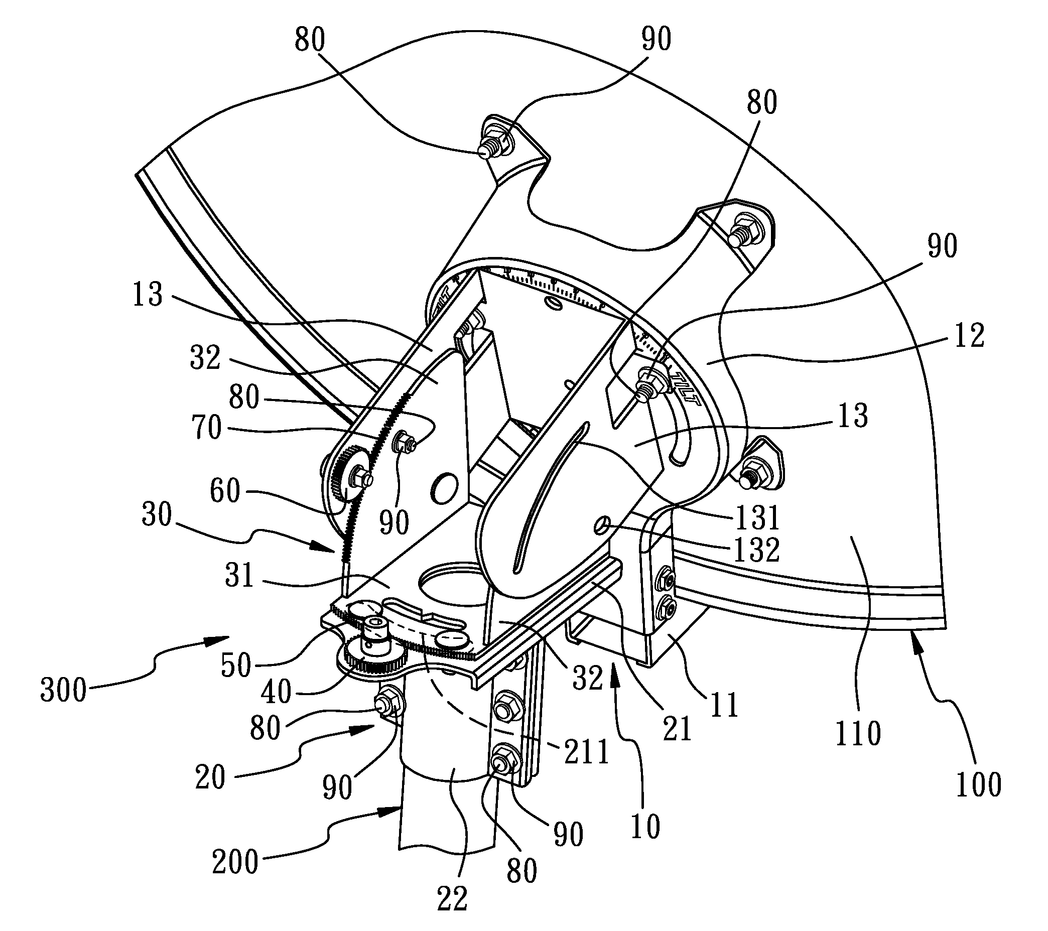
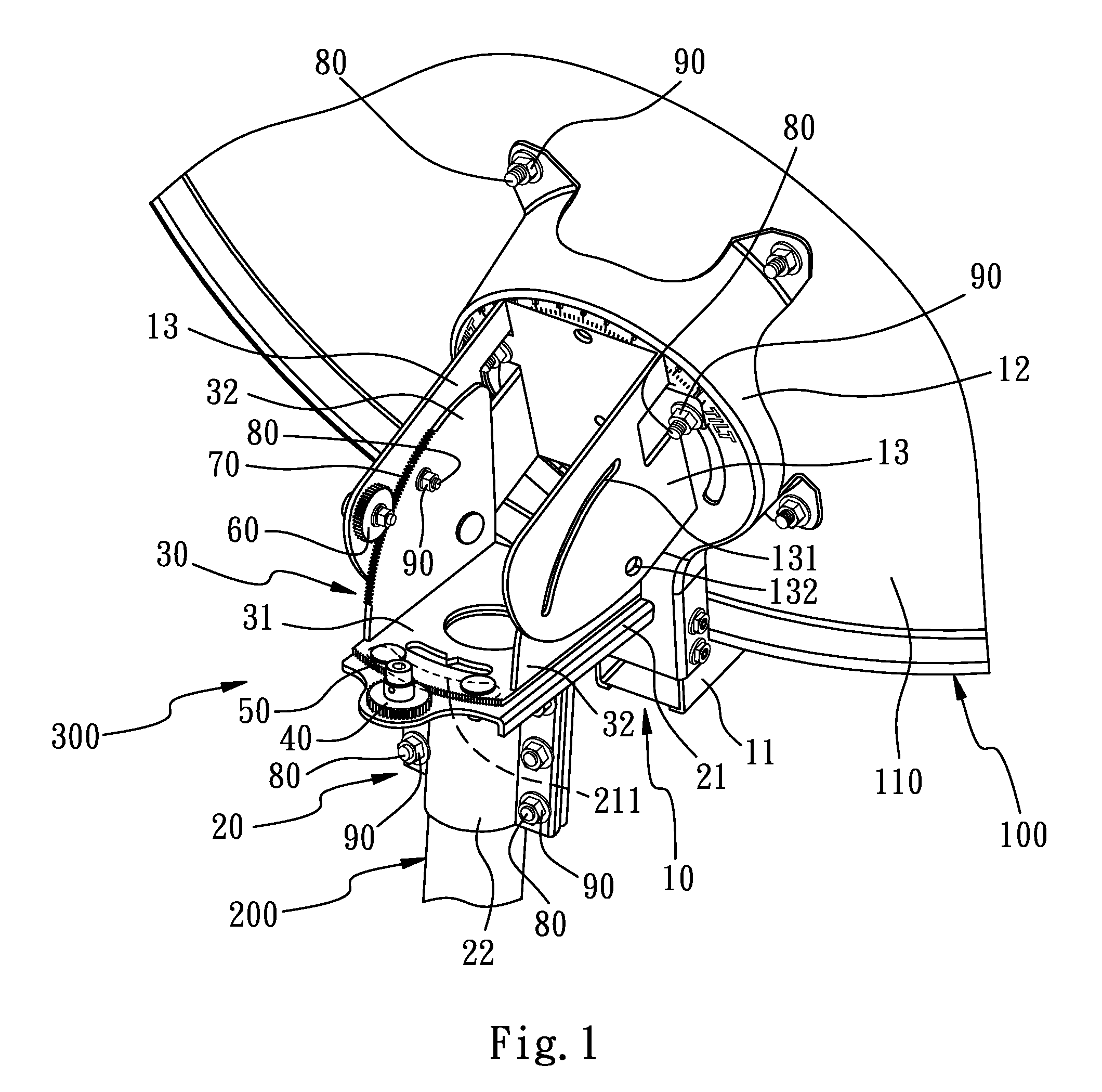
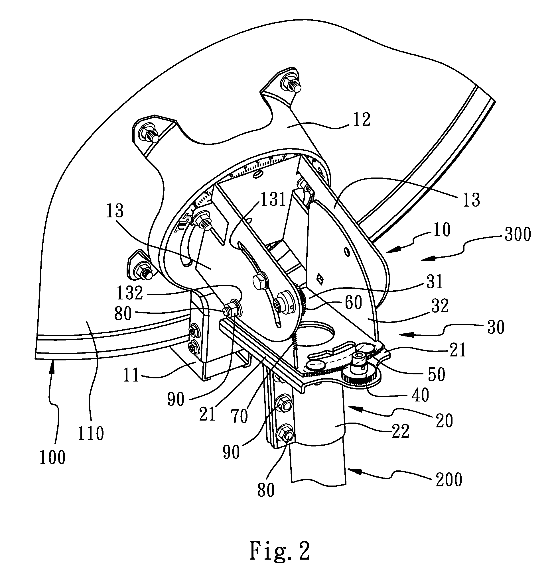
[0026]Referring to FIGS. 1 and 2, the present adjusting apparatus for the satellite antenna is for connecting between a satellite antenna 100 and an antenna support 200. The adjusting apparatus 300 includes a dish support 10, a supporting base 20, a connecting base 30, a first gear 40, a first row teeth 50, a second gear 60, a second row teeth 70, a plurality of screw bolts 80 and a plurality of screw caps 90.

[0027]The dish support 10 is for coupling to a dish 110 of the satellite antenna 100. The dish support 10 includes a bottom bracket 11, a clawed fixing bracket 12 and a coupling bracket 13. The fixing bracket 12 is locked to the dish 110 of the satellite antenna 100 by the screw bolts 80 and the screw caps 90. The bottom bracket 11 outwardly extends from the fixing bracket 12, inducing the peripheral fringe of the satellite antenna 100 abut against the bottom bracket 11. The coupling bracket 13 extends from the fixing bracket 12 toward a direction remote from the dish 110 of th...

second embodiment

[0035]Referring to FIG. 6, the present adjusting apparatus for the satellite antenna is for connecting between a satellite antenna 100 and an antenna support 200. The adjusting apparatus 400 includes a dish support 500, a supporting base 600, a connecting base 700, a first gear 40, a first row teeth 50, a second gear 60, a second row teeth 70, a plurality of screw bolts 80 and a plurality of screw caps 90.

[0036]Referring to FIGS. 7 and 8, the dish support 500 includes a main base 510 and a plurality of lugs 520. The lugs 520 are locked to the dish 110 of the satellite antenna 100.

[0037]The supporting base 600 includes a bottom wall 610, two sidewalls 620, an indent portion 630, and a fine adjusting hole 640 disposed on one of the sidewalls 620. The indent portion 630 being assisted by a clip 650, together with the screw bolts 80 and the screw caps 90 are clasped and abut on the antenna support 200.

[0038]The connecting base 700 includes a bottom wall 710, two sidewalls 720, an inner ...


PUM


Abstract

An adjusting apparatus for a satellite antenna of accurate and superfine adjustment and simple structure, includes a dish support, a supporting base, a connecting base, an X-direction fine adjusting mechanism and a Y-direction fine adjusting mechanism. The dish support couples to a dish of the satellite antenna. The supporting base couples to the antenna support. The connecting base connects between the dish support and the supporting base. The X-direction fine adjusting mechanism couples between the supporting base and the connecting base. The Y-direction fine adjusting mechanism couples between the connecting base and the dish support. The X-direction and Y-direction fine adjusting mechanisms respectively by means of the meshing relation between the gear and the row teeth to fine adjust, inducing the satellite antenna, relative to the antenna support, generate tiny range of motions along X and Y directions, respectively.

Description

BACKGROUND[0001]1. Field of the Invention[0002]The present invention relates to pedestals for adjusting satellite antennas, and more particularly, to an adjusting apparatus for a satellite antenna, capable of fine adjusting horizontal and perpendicular orientations of the satellite antenna accurately.[0003]2. Description of the Related Art[0004]Referring to the use of the satellite antennas, such as bow-tie antennas, for obtain better receiving angles, a conventional way is to dispose an adjusting pedestal, capable of adjusting angles, between the dish body of the satellite antenna and an antenna support. The adjusting pedestal provides adjusting operations along X and Y directions, by the adjustment allocation along X and Y directions, obtaining the most suited receiving angle, so that the electronic apparatus can obtain the clear and impurity-free signal receiving effect.[0005]The angle adjusting mechanisms of the conventional adjusting pedestals for the satellite antennas ordinar...

Claims


Application Information

Patent Timeline
IPC IPC(8): H01Q3/00
CPCH01Q3/08
Inventor TUNG, KANG HSI
Owner TUNG KANG HSI
Why Eureka
Try Eureka