Light emitting illuminant

a technology light source, which is applied in the field of light emitting illuminant, can solve problems such as producing an eye-sore effect, and achieve the effects of improving the eye-sore effect of light source, simple installation, and convenient application

Inactive Publication Date: 2010-05-27
PENG WU TE
View PDF2 Cites 2 Cited by
  • Summary
  • Abstract
  • Description
  • Claims
  • Application Information

AI Technical Summary

Benefits of technology

[0006]Therefore, it is a primary objective of the invention to provide a light emitting illuminant that features a simple installation and an easy and convenient application, and is capable of providing a strong light source to a light emitting device and changing the wavelength and direction of a mixed light to improve the eyesore effect of a light source, and amplify the wavelength of a focused / scattered light of the mixed light source or mix the light, so as to achieve a high brightness of the light source, and improve over the prior art.
[0007]Another objective of the present invention is to provide a light emitting illuminant having the features of a low manufacturing cost and a safe application.
[0008]To achieve the foregoing objectives, the present invention provides a light emitting illuminant that improves a cover of a conventional light emitting device by designing the internal surface of the cover with an irregular serrated surface, such that after a strong light source of the light emitting device is projected onto the internal surface of the cover, the wavelength and the reflecting / refraction direction of the light source are changed to achieve a mixed light effect and overcome an eyesore effect of the strong light source. The external surface of the cover is designed in an arc shape and with a thickness different from that of the internal surface to constitute a lens mode, such that after the lights of the light source are mixed through the internal surface, the lens with the property of focusing / scattering lights can change the wavelength to amplify and mix the lights, so as to provide a high brightness for the light source.

Problems solved by technology

The brightness of a light emitted from a light emitting device having a lower-intensity light source (such as a fluorescent lamp tube or a tungsten light bulb) falls within a comfortable range, but a light emitted from a light emitting device with a higher-intensity light source (such as an LED lamp or a projector lamp) will be too bright and produce an eyesore effect.

Method used


Image

  • Light emitting illuminant
  • Light emitting illuminant

Examples


Embodiment Construction

[0010]To make it easy for our examiner to understand the objects, characteristics and effects of the present invention, we use preferred embodiments with a related drawing for the detailed description of the present invention as follows:

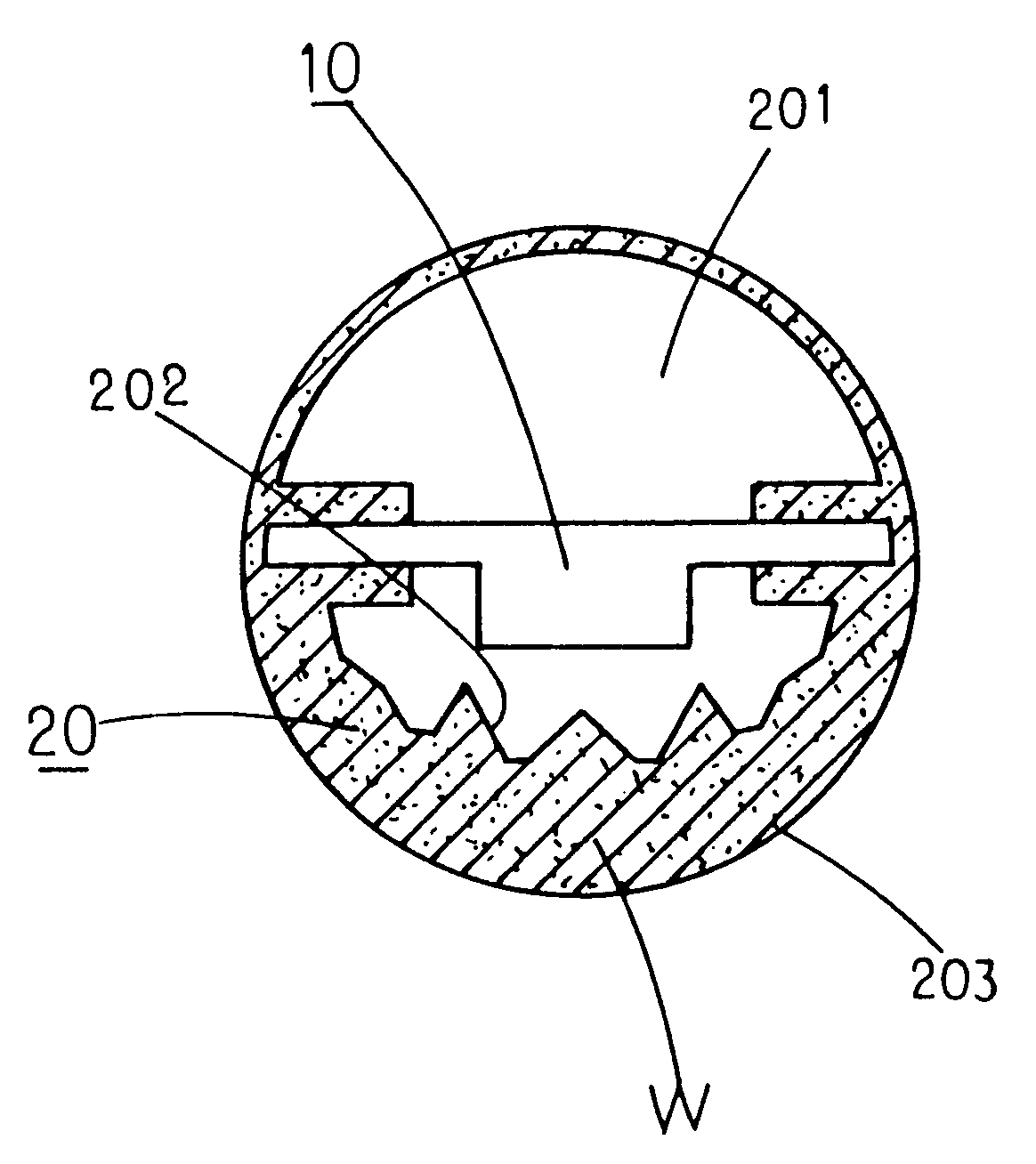
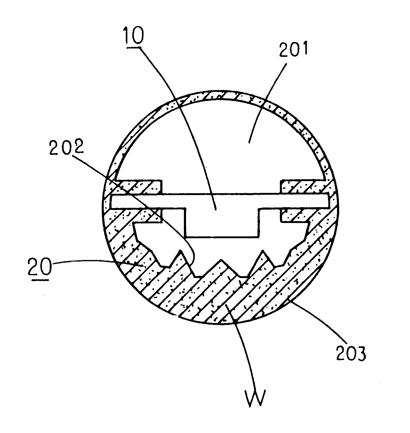
[0011]With reference to the FIGURE for a cross-sectional view of a light emitting illuminant in accordance with a preferred embodiment of the invention, the light emitting illuminant improves a cover 20 of a light emitting device 10, wherein the cover 20 is made of a transparent material and includes a hollow containing portion 201 for receiving a light emitting device 10 (such as an LED), a plurality of irregular serrated surfaces 202 on the internal surface corresponding to a light source emitted from the light emitting device 10, and the external surface 203 is in an arc shape, and the thickness W between the external surface 203 and the internal surface 202 of the cover 30 varies to form a lens mode, wherein the thickness between the internal and...


PUM


Abstract

A light emitting illuminant improves a cover of a conventional light emitting device by designing the internal surface of the cover with an irregular serrated surface, such that after a strong light source of the light emitting device is projected onto the internal surface of the cover, the wavelength and the reflecting/refraction direction of the light source are changed to achieve a mixed light effect and overcome an eyesore effect of the strong light source. The external surface of the cover is designed in an arc shape and with a thickness different from that of the internal surface to constitute a lens mode, such that after the lights of the light source are mixed through the internal surface, the lens with the property of focusing/scattering lights can change the wavelength to amplify and mix the lights, so as to provide a high brightness for the light source.

Description

BACKGROUND OF THE INVENTION[0001]1. Field of the Invention[0002]The present invention relates to a light emitting illuminating apparatus, and more particularly to a light emitting illuminant that features a simple installation and an easy and convenient application, and is capable of providing a strong light source to a light emitting device and changing the wavelength and direction of a mixed light to improve the eyesore effect of a light source, and amplify the wavelength of a focused / scattered light of the mixed light source or mix the light, so as to achieve a high brightness of the light source, and improve over the prior art.[0003]2. Description of the Related Art[0004]In general, most covers of a light emitting device have smooth surface on both internal and external sides of the covers and an even thickness. The brightness of a light emitted from a light emitting device having a lower-intensity light source (such as a fluorescent lamp tube or a tungsten light bulb) falls wit...

Claims


Application Information

Patent Timeline
Patent Type & Authority Applications(United States)
IPC IPC(8): F21V99/00
CPCF21K9/00F21Y2101/02F21V5/04F21V5/02F21Y2115/10F21K9/69
Inventor PENG, WU-TE
Owner PENG WU TE
Why Eureka
Try Eureka