
Method for making artificial turf

a synthetic grass and synthetic technology, applied in the direction of thin material handling, ways, constructions, etc., can solve the problems of drainage holes, poor dimensional stability of fabrics, and difficulty in achieving drainage holes

Active Publication Date: 2010-05-27
PRECISIONJET LLC
View PDF23 Cites 4 Cited by
  • Summary
  • Abstract
  • Description
  • Claims
  • Application Information

AI Technical Summary

Benefits of technology

[0012]It is an object of the present invention to produce an artificial athletic turf in which execution of the step of coating a tufted backing to achieve tuft lock may be precisely replicated on virtually every article of backing that is linearly tufted, irrespective of the actual spacing of their respective parallel rows of tufts. Consequently, the present invention eliminates the need to adjust coating machinery or modify coating technique in accordance with variations in tuft placement specifications of different articles of linearly tufted backing.
[0013]It is another object of the invention to create a synthetic turf product for use as an outdoor athletic turf without implementing any of the normal practices for achieving both tuft lock and sufficient drainage properties. Specifically, by employing a tuft locking technique that represents an unconventional step in conventional methods for producing artificial athletic turf, the present turf production method obviates the need to, for example, heat yarn tufts in order to tackify and thermoplastically bond them to the bottom face of a primary backing Consequently, the material cost associated with including a secondary backing that functions as a heat sink and protects the yarn pile which extends from the top face of the backing may be avoided. As another example, the present method renders unnecessary a precision driven coating dispenser that is capable of discretely placing thin lines of liquefied coating material precisely onto the spaced tuft rows formed within a particular backing. Alternatively, the instant method eliminates the additional step of perforating a continuously coated backing in order to recreate porosity after completing the steps of applying coating material to the backing and allowing the material to cure.

Problems solved by technology

Again, it is generally necessary to coat the bottom of the tufted backing in order to prevent yarn from dislodging during athletic use, but doing so can pose challenges that the prior art has evolved in effort to overcome.
Furthermore, since the spacing of their individual woven fibers may cause some woven fabrics to exhibit poor dimensional stability under the stress of athletic activity, putting the backing fibers in a common matrix with a coating layer should improve the stableness of the turf and render it less prone to stretch or otherwise deform during use.
Applying a continuous coating film to an athletic turf backing can present potential drawbacks, though.
For artificial turfs that are infilled, as most contemporary sports turfs are, these drainage holes can present challenges.
So, over time, the cumulative effects of climate exposure and stress imposed by athletic use may cause the drainage to stretch and exacerbate the problems related to their presence.
This simply accelerates the aforementioned maintenance demands, and ultimately, it shortens the useful life of the turf.
Not only is the material cost obviously greater, a continuous coating layer substantially increases the weight of the turf product and, thus, makes it more expensive to transport.
Of course, when fuel prices skyrocket as they did in 2008, this becomes a significant cost component in the turf product distribution and sale chain.
Therefore, the total cost of producing the turf product may be increased by the inclusion of a secondary backing sheet(s) that might not be needed if the yarn was bonded to the primary backing by way a separate coating material.
This can demand tedious work in adjusting coating delivery and shielding mechanisms between coating tasks.

Method used


Image

  • Method for making artificial turf
  • Method for making artificial turf
  • Method for making artificial turf

Examples


Embodiment Construction

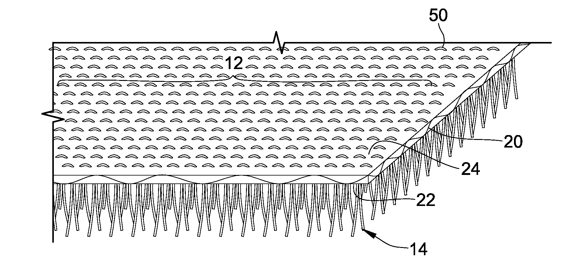
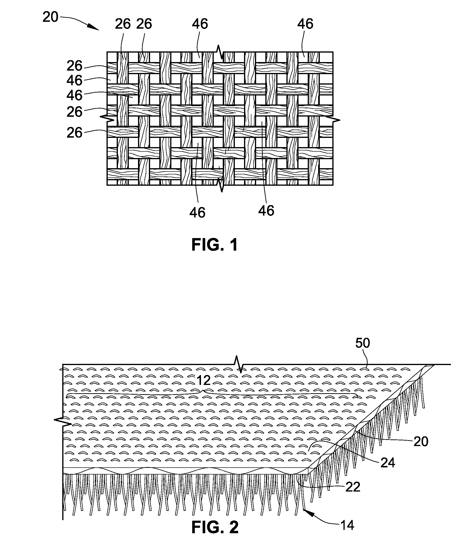
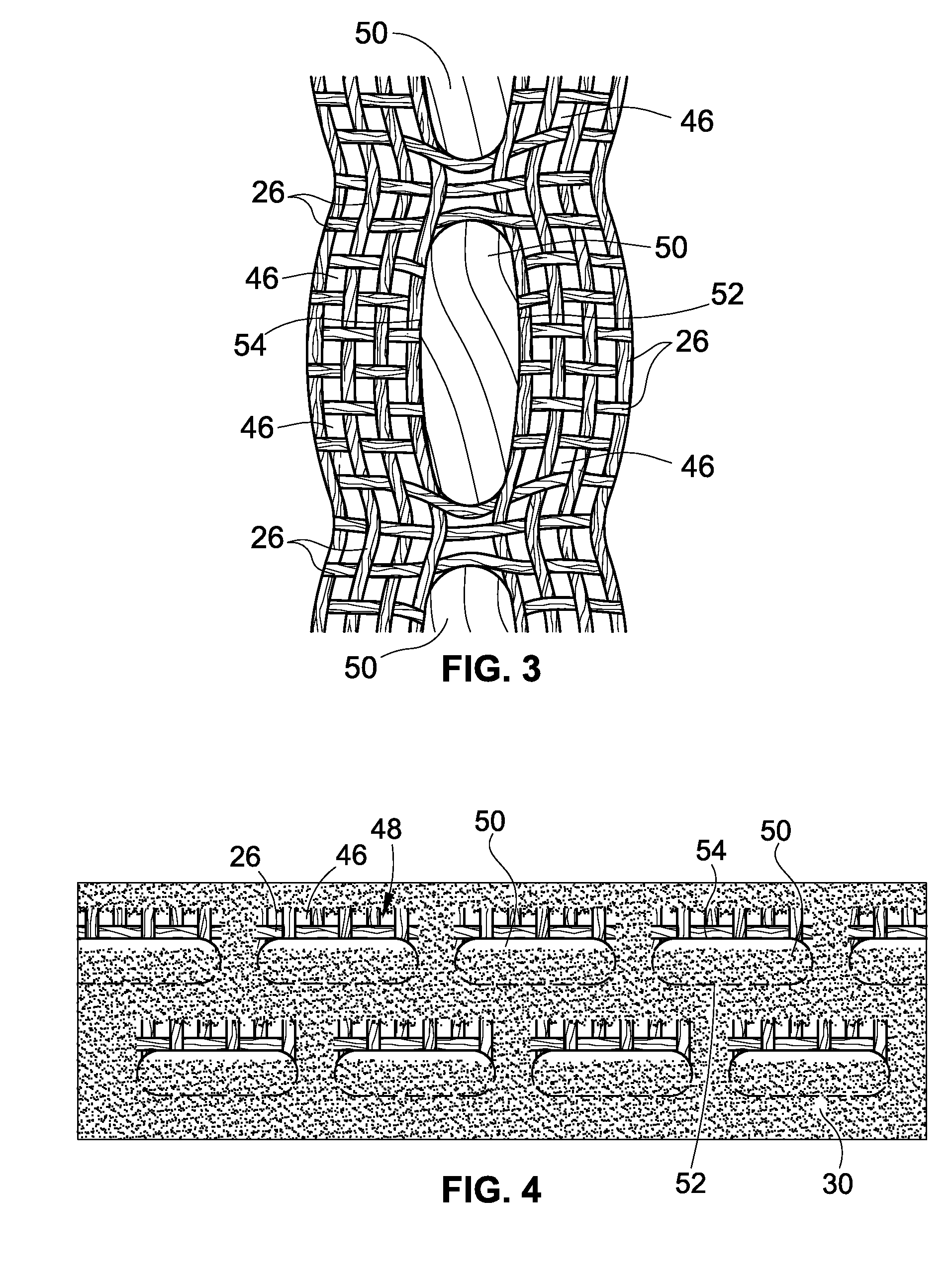
[0021]It should be understood that the present disclosure has particular applicability to the making of artificial turf that is intended for use as a sports playing surface, but can be applied to the manufacture of synthetic grass generally. This disclosure, as illustrated in the accompanying Figure drawings, relates to an artificial athletic turf comprising a backing 20 to which at least one yarn is mechanically adhered, first, via a tufting process and then via a spray coating process. Due to the particular way in which a discontinuous layer 30 of coating material is formed along its backing element 20 as shown in FIGS. 4 & 5, the turf remains adequately water permeable without having to be perforated after being coated.

[0022]The backing 20 may be constructed of polypropylene fabric or any other fabric commonly used for athletic turf, and it should be woven (or perforated, in the case of a nonwoven fabric) so that, even prior to being tufted and coated, it exhibits the porosity ch...


PUM


Abstract

An artificial athletic turf includes a backing having a top face and a bottom face, yarn tufted through the backing such that cut pile extends from the top face and backloops of yarn are closely adjacent the bottom face and a discontinuous coat is disposed over the backloops and bottom face in order to bind the yarn to the backing The coating material is sprayed onto the bottom face of the tufted backing at an inclination angle of less than 45 degrees to the plane of the backing and under conditions which cause sprayed material to bind the backloops to the backing, but not deposit along narrow areas of the backing between rows of backloops, thus, allowing the turf to remain porous in spots.

Description

BACKGROUND[0001]The present invention generally relates to methods for producing synthetic grass, and it is specifically directed to an improved method of applying adhesive to the stitches, or backloops, of the yarn that is tufted into a backing material—a method which represents a more efficient process for producing an artificial athletic turf that possesses desirable qualities relative to its water permeability and dimensional stability.[0002]Artificial turf has long been used as a playing surface for sports that are traditionally played on grass fields, such as football, baseball and soccer to name a few. In many parts of the country which experience exceedingly cold, rainy or dry weather during the times of year such sports are customarily played in organized leagues, an artificial turf playing surface can be virtually essential to playing outdoors. For example, an artificial turf may be preferable to natural grass for an outdoor football field in the Great Lakes region because...

Claims


Application Information

Patent Timeline
Patent Type & Authority Applications(United States)
IPC IPC(8): A41G1/00
CPCE01C13/08Y10T428/23979Y10T428/23993
Inventor BEARDEN, JOHN H.ENTERKIN, RANDAL A.
Owner PRECISIONJET LLC
Learn More