
Retro-percussive technique for creating nanoscale holes

a nano-scale hole and retro-percussive technology, applied in the field of patch clamping, can solve the problems of reducing the electrical resistance of the hole so formed, affecting the production of nano-scale holes in the plate structure, and spreading molten glass and debris on the exit of the hole, so as to achieve high resistance sealing and increase the ability of the pore

Active Publication Date: 2010-05-27
WISCONSIN ALUMNI RES FOUND
View PDF3 Cites 53 Cited by
  • Summary
  • Abstract
  • Description
  • Claims
  • Application Information

AI Technical Summary

Benefits of technology

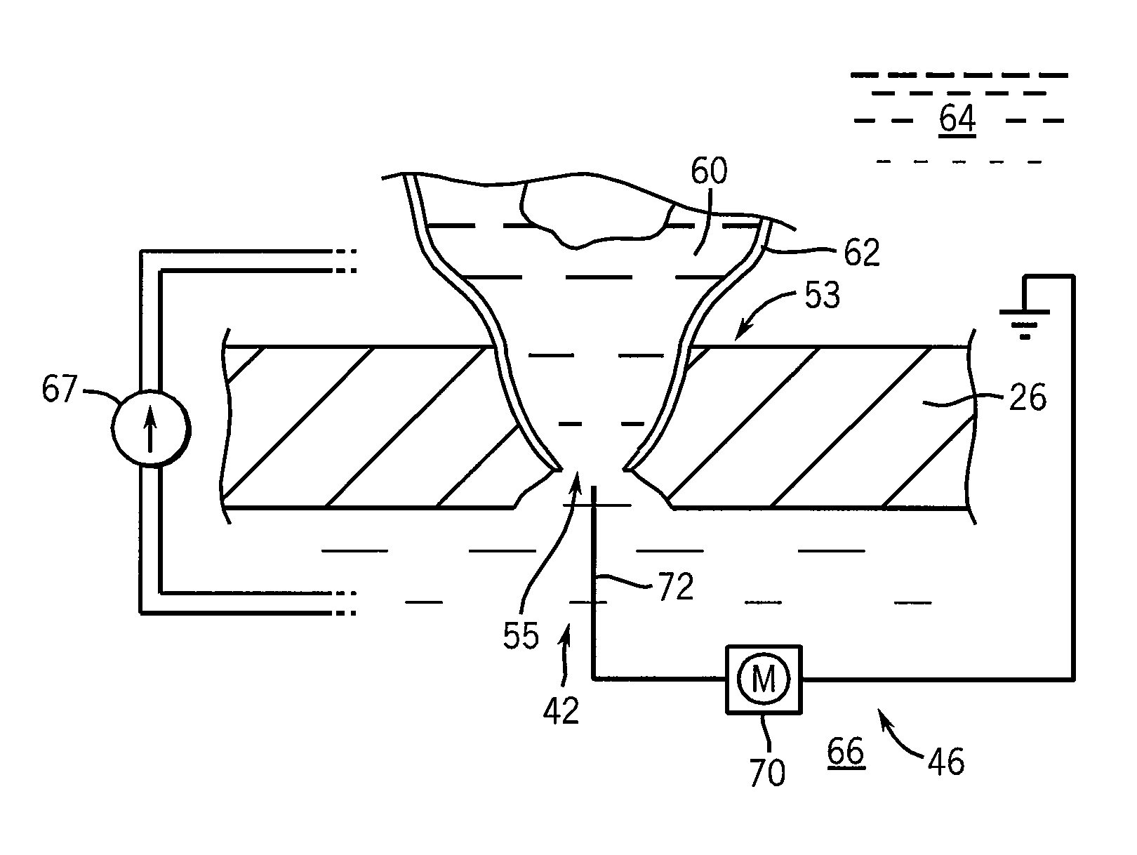
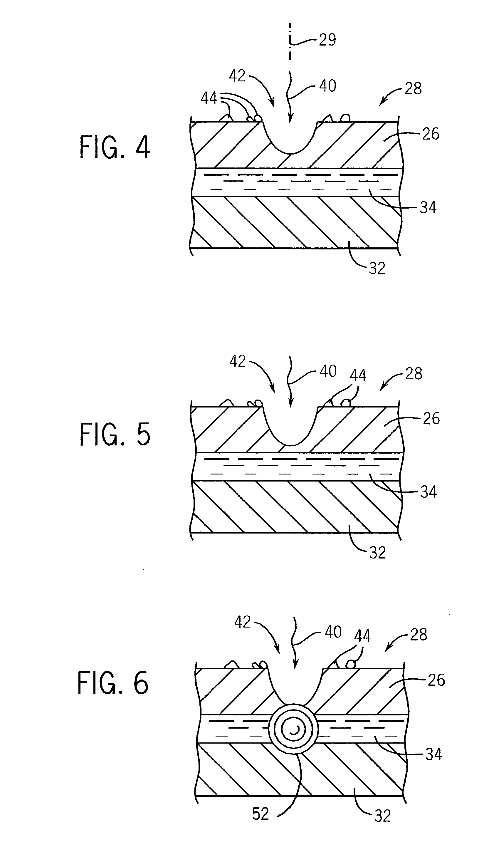
[0009]The present invention provides an improved technique for the generation of nanoscale-sized pores through a substrate using a laser. In the technique, the substrate is backed by a thermally expanding substance different from the substrate. In the final stages of hole formation, the thermally expanding substance, heated by the laser, produces a shock wave creating a counter-facing concave crater intersecting the front surface of a crater being created by the laser. The shock wave is such as to fire polish the pore exit, substantially increasing the ability of the pore to form high resistance seals with cell membranes. Fire polishing uses heat or flame to melt irregularities which then smooth under the influence of surface tension.
[0011]It is thus an object of at least one embodiment of the invention to provide nanoscale sized pores that have reduced debris onto the rear surface of the substrate as occurs during standard laser hole formation.
[0021]It is thus an object of at least one embodiment of the invention to provide an increased pressure wave for improved hole formation.

Problems solved by technology

The production of nanoscale holes in a plate structure is relatively difficult.
One disadvantage to the laser approach is that it spreads molten glass and debris on the exit of the hole.
This debris impedes proper adherence between the cell membrane and the lip of the hole leading to a reduction in the electrical resistance of the hole so formed.

Method used


Image

  • Retro-percussive technique for creating nanoscale holes
  • Retro-percussive technique for creating nanoscale holes
  • Retro-percussive technique for creating nanoscale holes

Examples


Embodiment Construction

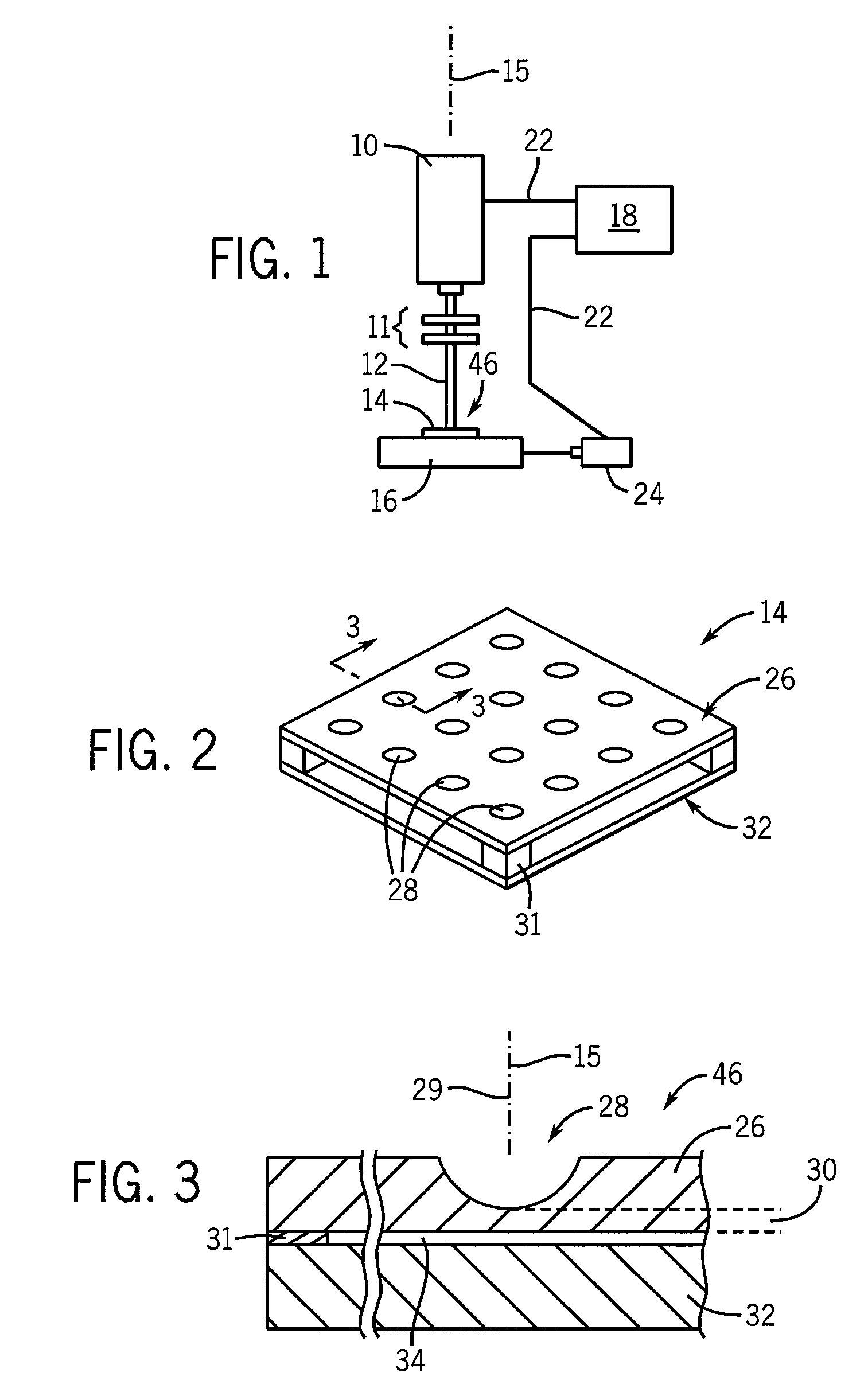
[0037]Referring now to FIG. 1, the present invention may use an excimer laser 10 having collimating and focusing optics 11 to direct a narrow collimated beam 12 of light along an axis 15 toward a front surface of a substrate assembly 14 held on a mechanical stage 16. The laser may, for example, have a frequency range of 192 to 157 nm.

[0038]The laser 10 and stage 16 may be controlled by an automated controller 18 of the type well known in the art providing control signals 22 to the laser 10 controlling its output power in a series of pulses as will be described and providing control signals 22 to actuator motors 24 providing x-y control of the stage 16.

[0039]Referring now to FIGS. 2 and 3, the substrate assembly 14 may include an upper substrate 26, for example, a borosilicate cover slip having a thickness of approximately 150 microns. A front surface of the upper substrate 26 may have a series of depressions or wells 28 formed at regular x-y grid locations 29. The wells 28 provide a...


PUM

PropertyMeasurementUnit
Diameteraaaaaaaaaa
Nanoscale particle sizeaaaaaaaaaa
Thicknessaaaaaaaaaa

Abstract

A method of forming extremely small pores in glass or a similar substrate, useful, for example, in patch clamp applications, that employs a backer plate to contain energy of a laser-induced ablation through the front surface of the substrate so as to create a rear surface shock wave providing a fire polishing of the exit aperture of the pore such as produces improved sealing with cell membranes.

Description

STATEMENT REGARDING FEDERALLY SPONSORED RESEARCH OR DEVELOPMENTCROSS REFERENCE TO RELATED APPLICATIONBACKGROUND OF THE INVENTION[0001]The present invention relates to “patch clamping” for investigating ionic and molecular transport through cellular membranes via ion channels and, in particular, to a substrate providing a set of nano to microscale pores that may be readily sealed to cellular membranes.[0002]The lipid bilayers that make up cell membranes include ion channels that control the flow of ions into and out of cells. Certain ion channels open in response to signaling molecules including naturally occurring signaling molecules and drug molecules. In the development of therapeutic drugs, it is necessary to determine the effect of the drug on ion channels either to avoid adverse effects or to create a positive therapeutic effect for the treatment of ion-channel related diseases.[0003]Analysis of the response of ion channels may be conducted with a so-called “patch clamp”, tradi...

Claims


Application Information

Patent Timeline
IPC IPC(8): B32B3/10B29C35/08B23K26/00B23K26/36B23K26/382
CPCB23K26/388Y10T428/24281Y10T428/24273B23K26/389
Inventor BLICK, ROBERT H.YU, MINRUIQIN, HUAKIM, HYUN-SEOK
Owner WISCONSIN ALUMNI RES FOUND
Learn More