

Bladder for a Ball
a technology for a blade and a ball, which is applied in the field of blades for inflatable balls, can solve the problems of cable, its contacts or the connected components being damaged, and not suitable to withstand the dynamic requirements of a ball, so as to avoid damage to the wires, avoid excessive pulling loads, and advantageous for the stability of the wiring
- Summary
- Abstract
- Description
- Claims
- Application Information
AI Technical Summary
Benefits of technology
Problems solved by technology
Method used
Image


Examples
Embodiment Construction
[0022]In the following, embodiments of the invention are further explained with reference to the example of a bladder for a soccer ball. However, it is to be understood that the present invention is not limited for use in a soccer ball. Other balls with an inflatable bladder, such as handballs, basketballs, volleyballs, rugby balls, balls for American football etc., may also be provided with a wiring as described below. However, the present invention may provide particularly significant advantages for use in a soccer ball, since a soccer ball is subject to particularly great deformations during a soccer game, which is why the wirings of the bladder known from the prior art often fail.
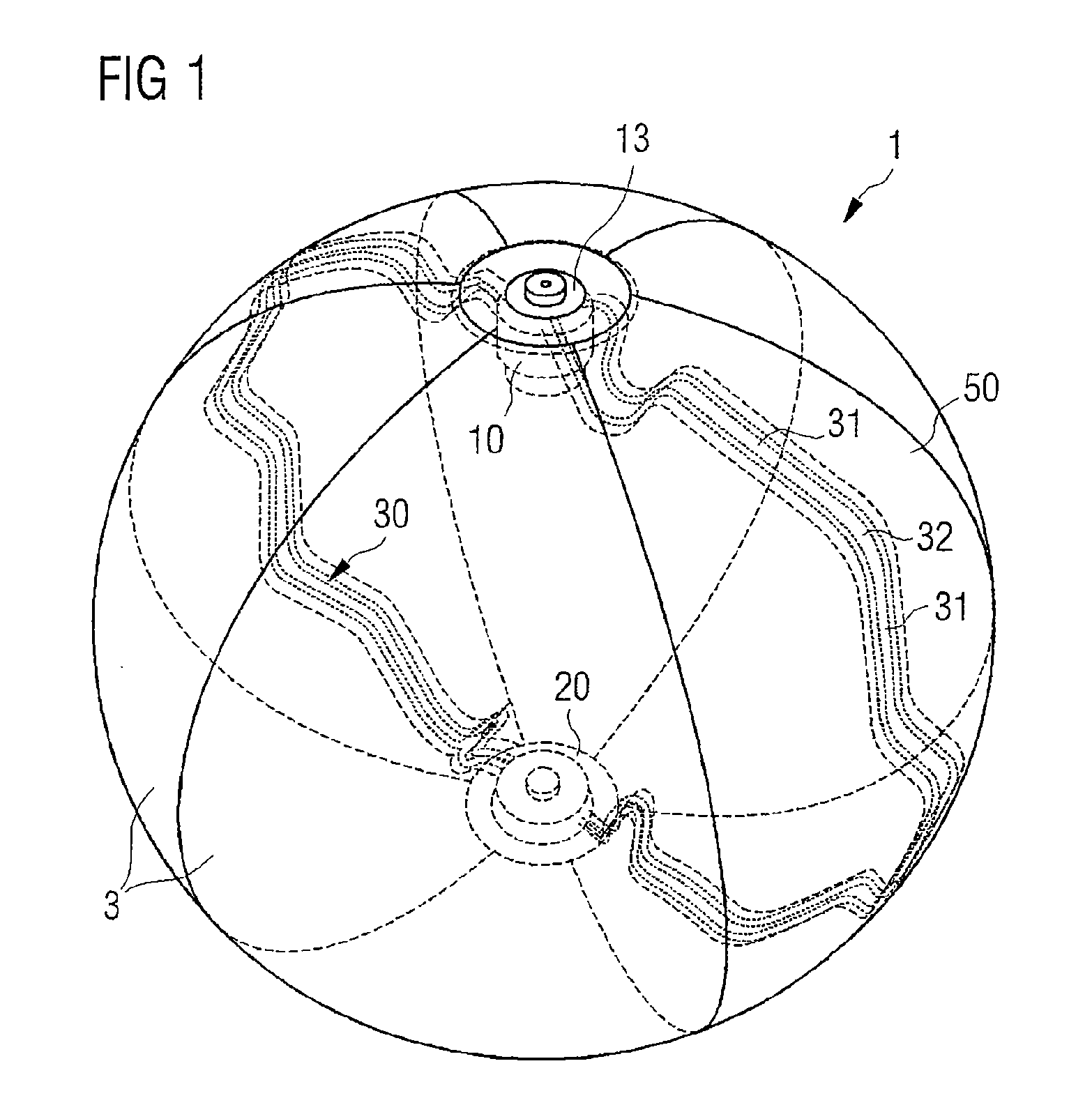
[0023]FIG. 1 shows an embodiment of the bladder 1. The bladder 1 may be manufactured from a plastic material. As can be seen, the bladder 1 of the embodiment in FIG. 1 may have six segments 3 extending essentially from the top of the bladder 1, the “north pole”, to the lower end of the bladder 1, the “s...
PUM
 Abstract
Description
Claims
Application Information