Turbine frame assembly and method for a gas turbine engine
a gas turbine engine and turbine frame technology, applied in the direction of machines/engines, stators, liquid fuel engines, etc., can solve the problem that none of these turbine frame configurations integrates a one-piece turbine frame construction with conventional-configuration active cooling nozzles
- Summary
- Abstract
- Description
- Claims
- Application Information
AI Technical Summary
Benefits of technology
Problems solved by technology
Method used
Image
Examples
Embodiment Construction
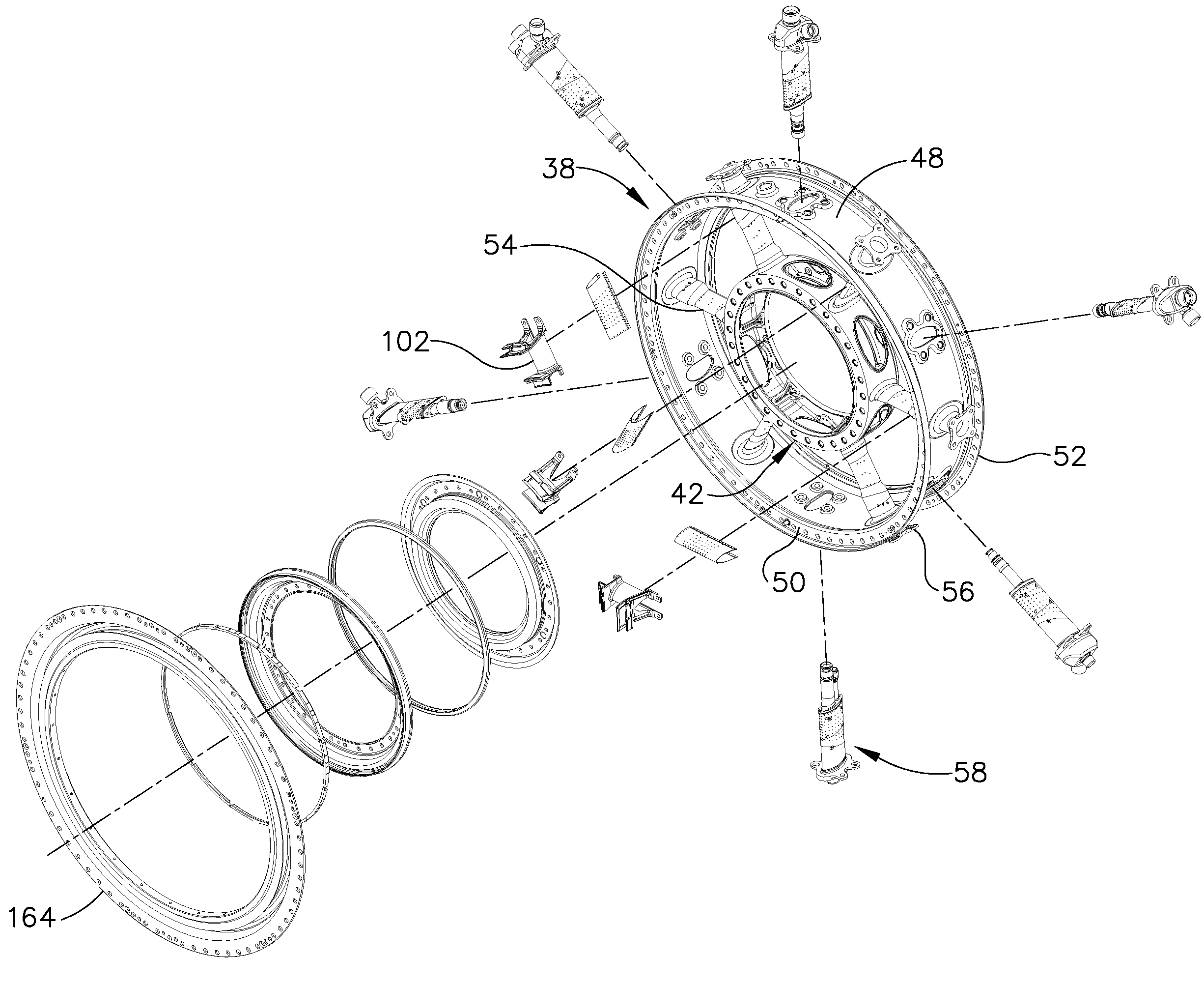
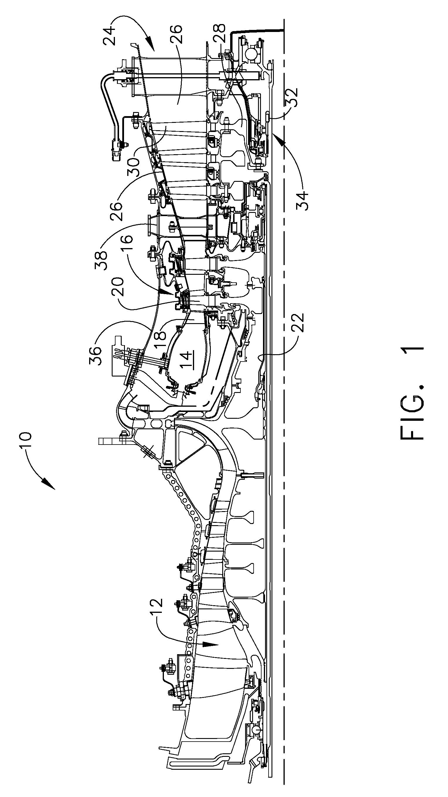
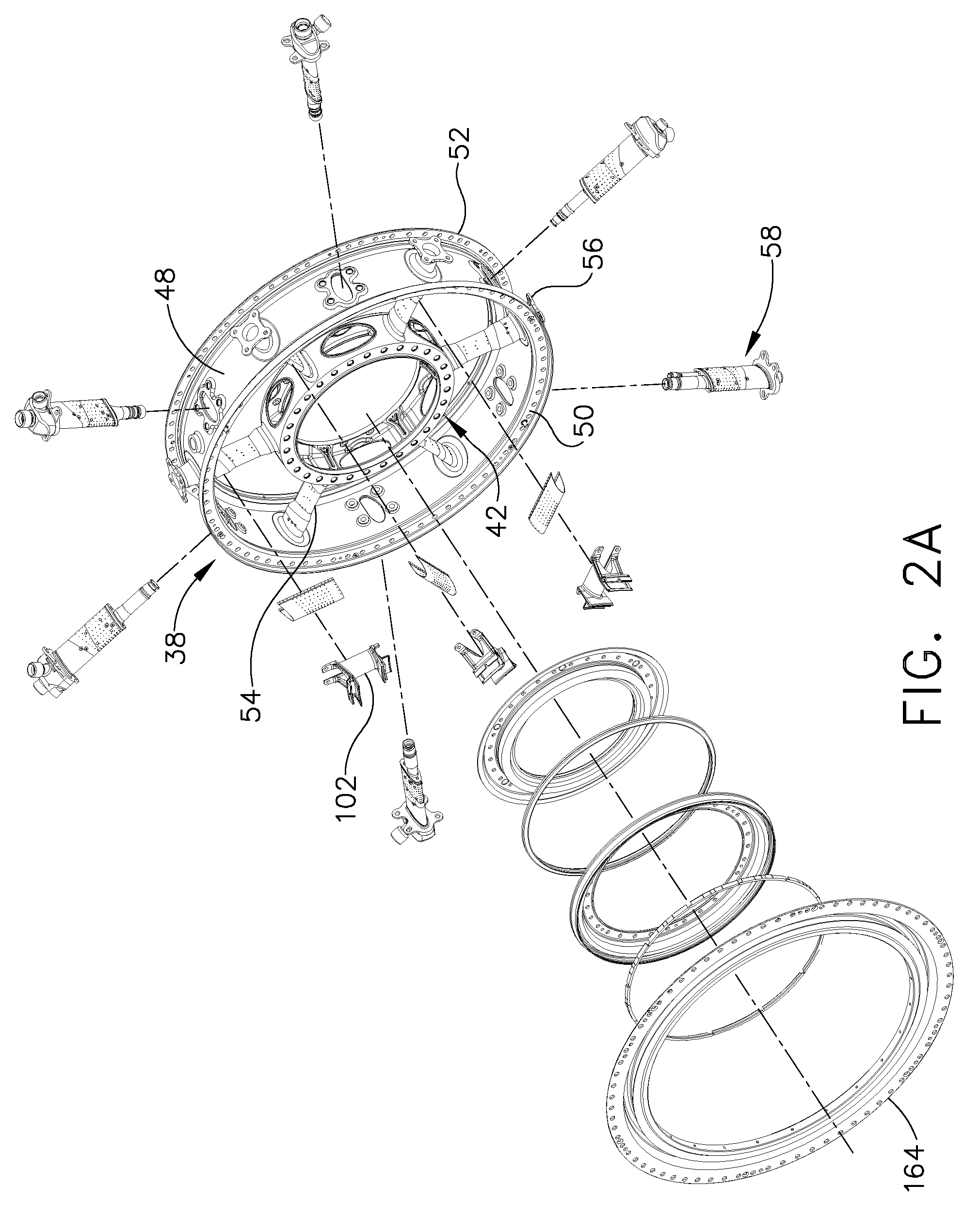
[0022]Referring to the drawings wherein identical reference numerals denote the same elements throughout the various views, FIGS. 1 and 2 depict a portion of a gas turbine engine 10 having, among other structures, a compressor 12, a combustor 14, and a gas generator turbine 16. In the illustrated example, the engine is a turboshaft engine. However, the principles described herein are equally applicable to turboprop, turbojet, and turbofan engines, as well as turbine engines used for other vehicles or in stationary applications.
[0023]The compressor 12 provides compressed air that passes into the combustor 14 where fuel is introduced and burned to generate hot combustion gases. The combustion gases are discharged to the gas generator turbine 16 which comprises alternating rows of stationary vanes or nozzles 18 and rotating blades or buckets 20. The combustion gases are expanded therein and energy is extracted to drive the compressor 12 through an outer shaft 22.
[0024]A work turbine 24...
PUM
 Abstract
Description
Claims
Application Information
 - R&D
- Intellectual Property
- Life Sciences
- Materials
- Tech Scout
- Unparalleled Data Quality
- Higher Quality Content
- 60% Fewer Hallucinations
Browse by: Latest US Patents, China's latest patents, Technical Efficacy Thesaurus, Application Domain, Technology Topic, Popular Technical Reports.
© 2025 PatSnap. All rights reserved.Legal|Privacy policy|Modern Slavery Act Transparency Statement|Sitemap|About US| Contact US: help@patsnap.com


