Railway Vehicle Comprising Pivoting Bogies

a technology of pivoting bogies and railways, which is applied in the direction of rail engagement elements, axle box mounting, locomotives, etc., can solve the problems of narrow corridors, inability to pass easily by passengers, and inability to easily mount the bogies by pivoting connections under the body

Active Publication Date: 2010-06-03
ALSTOM TRANSPORT TECH SAS
View PDF32 Cites 15 Cited by
  • Summary
  • Abstract
  • Description
  • Claims
  • Application Information

AI Technical Summary

Benefits of technology

[0156]The second embodiment of the invention also has many advantages.

Problems solved by technology

This bogie cannot easily be mounted by pivot connection means beneath the body.
The corridor would then become so narrow that it would not be possible for passengers to pass easily.

Method used


Image

  • Railway Vehicle Comprising Pivoting Bogies
  • Railway Vehicle Comprising Pivoting Bogies
  • Railway Vehicle Comprising Pivoting Bogies

Examples


first embodiment

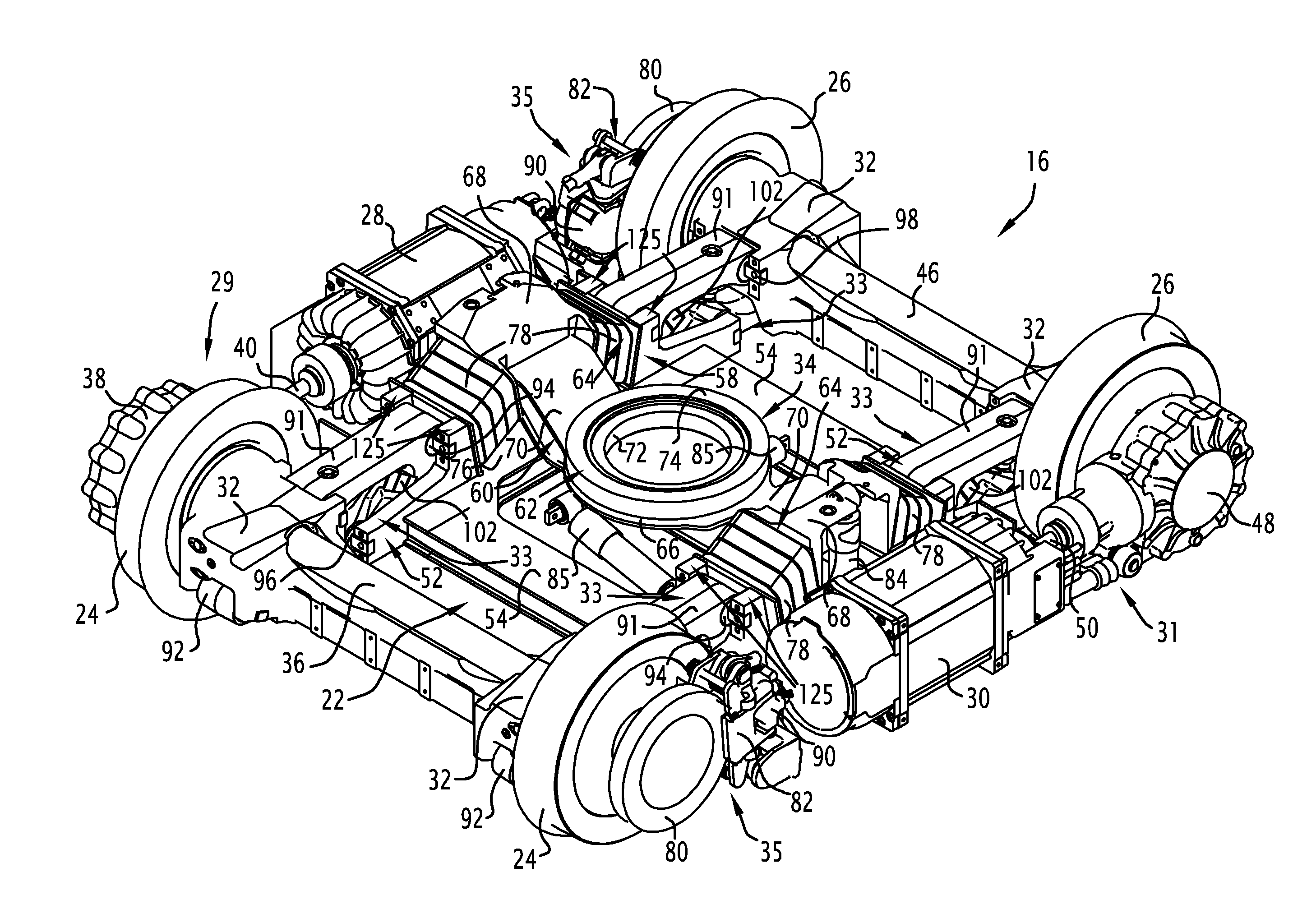
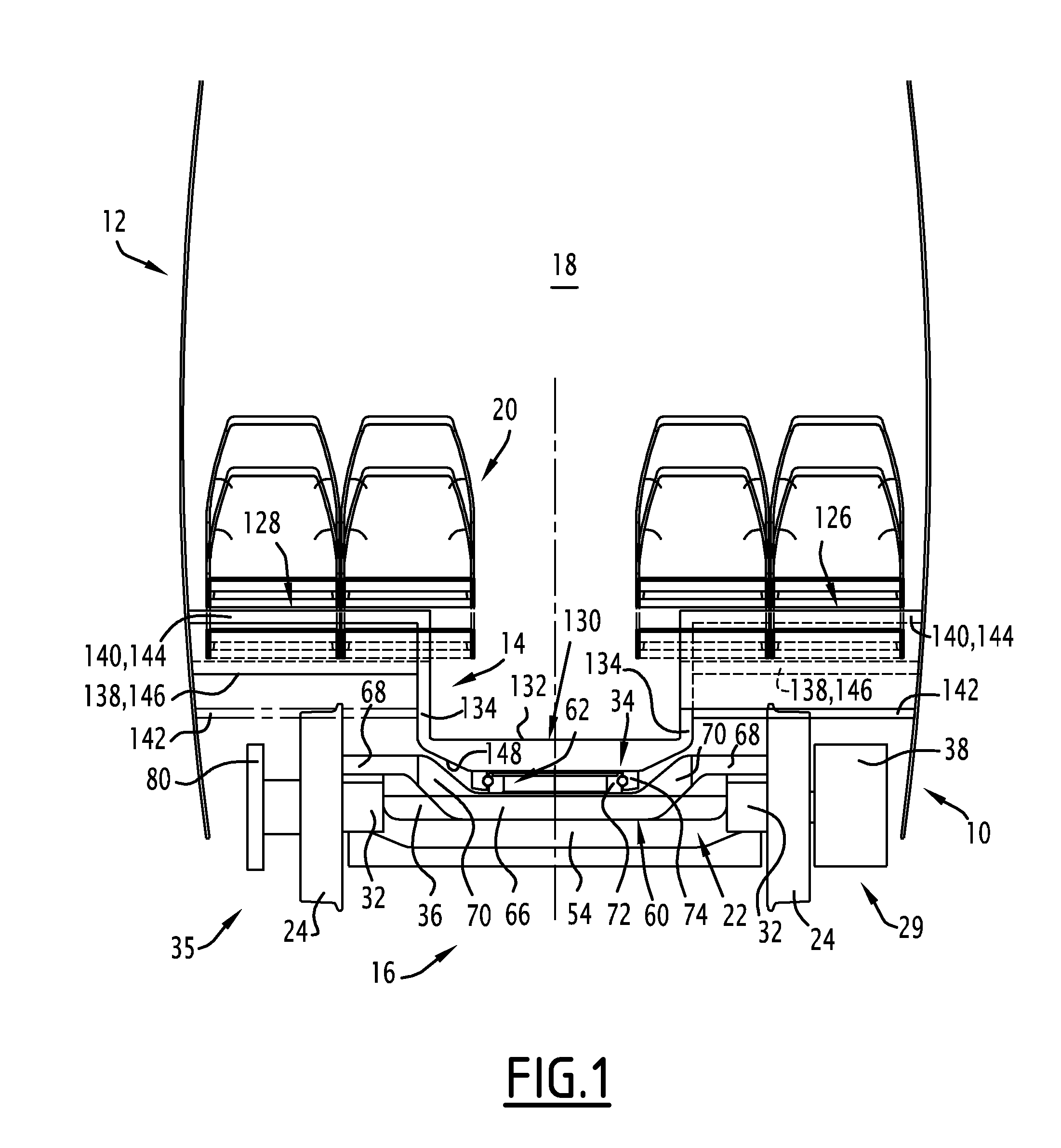
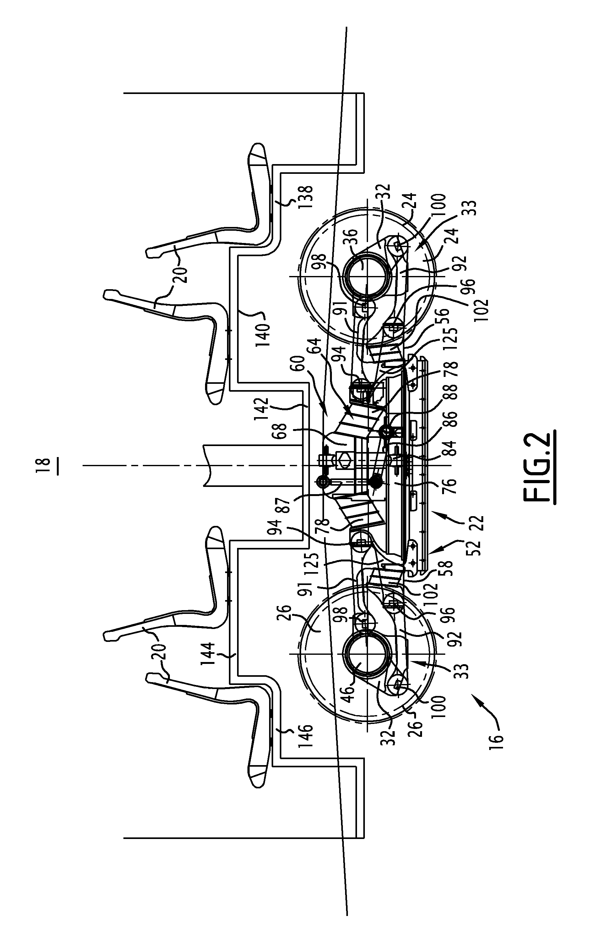
[0061]In the invention, each bogie comprises, as shown in FIG. 3, a bogie chassis 22; two front wheels 24 and two rear wheels 26; a motor 28 for driving the front wheels 24 and means 29 suitable for coupling the motor 28 to the front wheels 24; a motor 30 for driving the rear wheels 26 and means 31 suitable for coupling the motor 30 to the rear wheels 26; for each front wheel 24 and each rear wheel 26, an axle box 32 and a primary suspension device 33 of the chassis 22 on the axle box 32; pivot connection means 34 suitable for connecting the bogie 16 to the body 12; and front and rear brakes 35.

[0062]The front wheels 24 are coaxial, spaced transversely from one another, and are connected to the chassis 22. Similarly, the rear wheels 26 (FIG. 2) are coaxial, spaced transversely from one another, and connected to the chassis 22. The front wheels 24 are spaced longitudinally from the rear wheels 26.

[0063]As shown in FIG. 3, the front coupling means 29 comprise for example a front axle ...

second embodiment

[0116]Only the points in which the second embodiment differs from the first will be detailed below.

[0117]Each bogie 16 comprises a single motor 150 suitable for driving both the front and rear wheels. The front reducing gear 38 is coupled to the shaft of the single motor 150 by means of the front coupling 40, the rear reducing gear 48 being coupled to the shaft of the motor 150 by means of the rear coupling 50.

[0118]The motor 150, reducing gears 38 and 48 and couplings 40 and 50 are arranged between, on the one hand, a longitudinal plane P1 midway between the front wheels 24 and midway between the rear wheels 26 and, on the other hand, a plane P2 passing through the right front and rear wheels 24 and 26 (see FIG. 7). Thus, the motor 150, reducing gears 38 and 48 and couplings 40 and 50 are all arranged on the right side of the bogie, towards the inside of the bogie relative to the wheels. The reducing gears 38 and 48 are placed immediately inside the right front 24 and rear 26 wheel...


PUM


Abstract

A railway vehicle including a plurality of bogies is provided. Each bogie includes a chassis, two front wheels and two rear wheels. For each front wheel and each rear wheel, a guidance device is provided for guiding the wheel in rotation and a primary suspension device of the chassis is provided on the guidance device. At least the primary suspension devices associated with the front and rear wheels are arranged on the same first lateral side of the bogie. The primary suspension devices each include two longitudinal connecting rods, each connected by a first connection point to the chassis and by a second connection point to the corresponding guidance device and at least one resilient component inserted between the two connecting rods to define at least the vertical stiffness of the primary suspension device, the two connecting rods being offset longitudinally relative to one another. Each of the bogies also includes a pivot connection device for connecting the bogie to the railway vehicle.

Description

[0001]The invention relates in general to railway vehicles, particularly trams.[0002]More precisely, the invention relates to a vehicle supported by bogies mounted by pivot connections to the vehicle and allowing wide low corridors to be arranged in the vehicle. Such a vehicle is described in patent application CZ 2000-46 91.[0003]An object of the invention is therefore to propose a variant of the vehicle described in document CZ 200-4691. More precisely, the invention relates to a railway vehicle supported by bogies, each bogie being of the type comprising:[0004]a chassis;[0005]two front wheels and two rear wheels;[0006]for each front wheel and each rear wheel, guidance means for guiding the wheel in rotation and a primary suspension device of the chassis on the guidance means.BACKGROUND[0007]Such a bogie is known from document WO-00 / 64721, which describes a tram comprising a body and at least one powered bogie of this type. The side members of the bogie chassis are placed immediat...

Claims


Application Information

Patent Timeline
Patent Type & Authority Applications(United States)
IPC IPC(8): B61F3/04B61D1/00B61D17/10B61D13/00
CPCB61D13/00B61F5/325B61F3/04B61F5/32
Inventor RODET, ALAINECHE, CHRISTOPELONGUEVILLE, YVESDEMARQUILLY, FRANCIS
Owner ALSTOM TRANSPORT TECH SAS
Why Eureka
Try Eureka