
Shaping tool

Inactive Publication Date: 2010-06-03
BUSCH GERT
View PDF28 Cites 17 Cited by
  • Summary
  • Abstract
  • Description
  • Claims
  • Application Information

AI Technical Summary

Benefits of technology

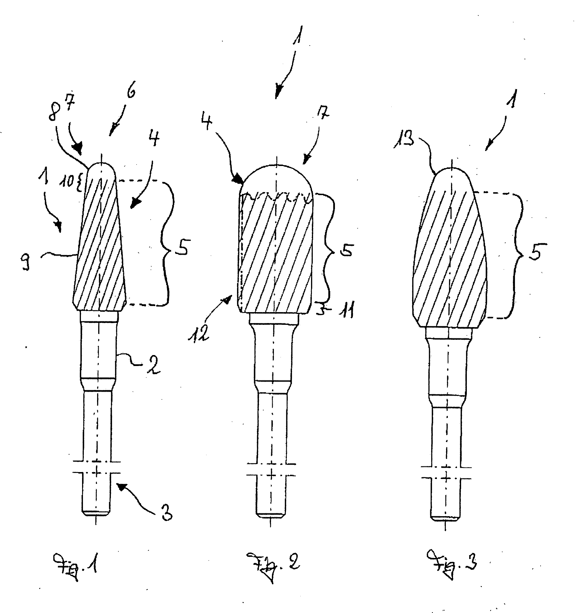
[0008]It has been shown to be useful if, on the one hand, the domelike region has a rounded-off part. This makes it possible to avoid the risk of injury which is inherent in the prior-art shaping tools especially due to the edged design. Since, in addition, it was found to be especially useful to dispense with a surface-shaping function that is inherent in the operative zone, i.e., to omit this region of the domelike structure completely, the shaping tool can be placed on the surface of the extremities without, however, itself abrasively shaping the surface. As already mentioned above, “abrasive” in the context of the proposed technical teaching of the present invention is meant to indicate that, because of the surface shaping function inherent in the operative zone, material can be removed from the surface. This can be done, for example, by means of an abrasive method, a cutting method or by means of some other method. Preferably, the domelike structure is smooth, and if a metal is used, it is polished. Thus, for example, when the shaping tool is used, it is possible to first place it on the surface and subsequently cautiously approach the area on which a surface of the body extremity is to be actually shaped. Only by tilting the shaping tool and / or by moving the shaping tool down to a deeper level is it possible for the operative zone to come into contact with the surface and for abrasive removal of material from the surface to take place.
[0014]The domelike structure preferably has a rotationally symmetrical design. On the one hand, this type of design simplifies production. On the other hand, it ensures that whenever the domelike structure first approaches a surface of the body extremity, the shaping tool at all times has the same contact surface, especially when the domelike structure is a full dome which has a shape which neither by way of concavities, indentations nor the like deviates from the prespecified domelike structure but still allows the domelike structure to be recognizable as the dominant geometry. In another embodiment, however, such can be present. This can be implemented, for example, in that, starting along the operative zone, the domelike structure begins to take on a hemispherical shape, with the surface, when viewed along the circumference, having concavities, such as are similarly known, for example, from a citrus press. Thus, when the shaping tool approaches the surface, this shape immediately informs the user that contact between the surface to be shaped and the shaping tool has been made. For example, mild unease on the part of the user, which is signaled by the irregular shape of the domelike structure, immediately alerts the user that contact has been made and thus it is ensured that at the same time, a difference is noted when the operative zone comes into contact with the surface to be shaped or when only the domelike structure makes contact with the surface to be shaped. For example, the operative zone can also have elevations or grooves which, on contact with the surface to be shaped, also alert the user, thereby again providing him / her with information that the operative zone is touching the surface.
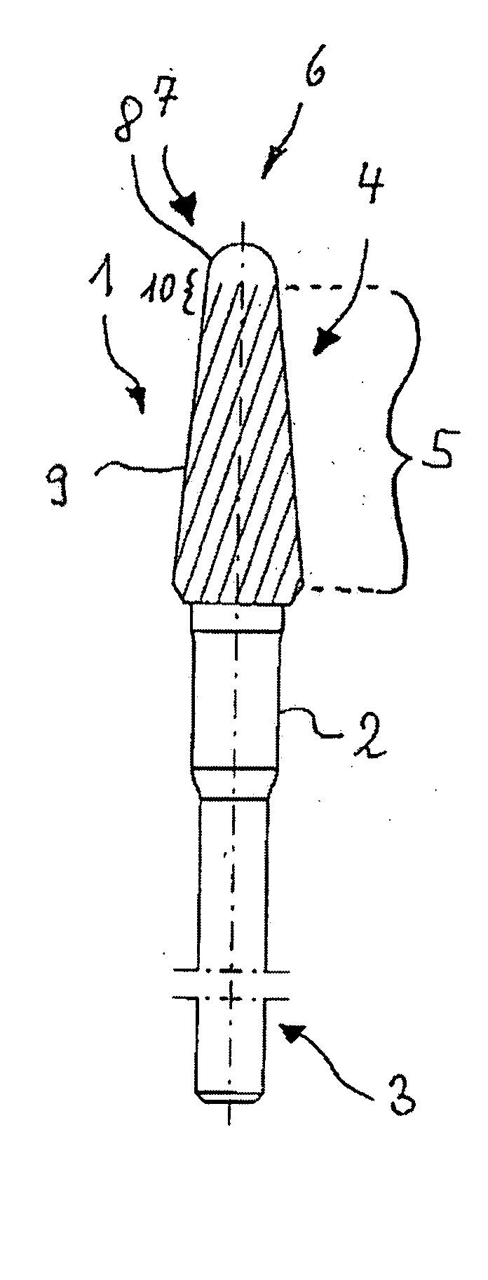
[0016]According to another embodiment, a surface of the domelike structures transitions steplessly into a surface of the operative zone. Because of the stepless transition, the risk of injury during use of the shaping tool is prevented since there are no sharp edges, such as the ones present in other prior-art shaping tools. This also allows the shaping surface of the operative zone to steplessly transition into the domelike structure. In this manner, it is again possible to avoid a stepped edge which could carry the risk of injury when the shaping tool is used. Preferably, the operative zone is disposed in a recess in the operative section in the longitudinal direction of the shaping tool. In this manner, the recess can be filled, for example, with an abrasive material, and thus the shaping surface of the operative zone can be made to conform uniformly to a surface of the domelike structure. In addition, the possibility of disposing a recess in the operative section, it is also possible to prevent unintended contact between the operative zone and the surfaces of the extremities to be shaped. To this end, but also independently thereof, one embodiment provides that the domelike structure project beyond the operative zone, thereby also offering a certain protection. Thus, for example, the diameter of the domelike structure can be dimensioned in such a manner that at least in one section, it is larger than a diameter of the operative zone.

Problems solved by technology

When working on the foot or the hand, in particular the nails and the skin, the use of the shaping tool, in particular when known cutting or abrasive tools are used carelessly, entails the risk of injury to the extremity due to the surface-effective, in particular abrasive, i.e., material removing and / or abrading zone of the shaping tool.
This carries risks especially for diabetics and for other categories of individuals who are suffering from certain disorders.

Method used


Image

  • Shaping tool
  • Shaping tool

Examples


Embodiment Construction

[0024]FIG. 1 shows a first embodiment of a shaping tool 1. Using this shaping tool 1, it is possible to treat a surface of a body extremity. To this end, the shaping tool 1 comprises a shaft 2 which can be continuous or stepped. One shaft end 3 can be clamped. To this end, the shaft end 3 of the shaft 2 can have grooves or other recesses in the shaft which make it possible to transmit a rotational force. Another possibility is that instead of the recesses, the shaft end 3 has elevations. In addition, however, the shaft end 3 can also be exclusively cylindrical as shown in the figure, in which case a torque transmission takes place by clamping the shaft end 3 into an appropriately designed holder. At the end opposite to the shaft end 3, an operative section 4 is disposed. The operative section 4 comprises an operative zone 5. This operative zone can be formed, for example, by cutting blades and / or an abrasive material. In addition, on the end opposite to the shaft end 3, the operativ...


PUM


Abstract

The present invention relates to a rotating shaping tool (1) designed to treat a surface of body extremities of mammals, in particular the nails or the skin of humans, which tool comprises an elongated shaft (2), one end (3) of which shaft can be clamped and the other end of which shaft has an operative section (4) with a rotationally symmetrical operative zone (5) which shapes the surface while abrasively removing parts of the surface and which projects beyond a shaft diameter, with the operative zone (5) on the end opposite to the shaft end (3) that is to be clamped being bounded by a rounded part (6) having a domelike structure (7) without the surface-shaping function that is inherent in the operative zone (5).

Description

CROSS-REFERENCE TO RELATED APPLICATIONS[0001]This application claims priority of German Patent Application 202008015821.4 filed on Dec. 1, 2008.FIELD OF THE INVENTION[0002]The present invention relates to a shaping tool for use in the treatment of a surface of body extremities of mammals, in particular the nails or the skin of humans. To this end, a rotating shaping tool is used, which tool has an elongated shaft, one end of which shaft can be clamped and the other end of which shaft holds an operative section with a rotationally symmetrical operative zone, which operative section shapes the surface while abrasively removing parts of the surface and which projects beyond a diameter of the shaft.BACKGROUND OF THE INVENTION[0003]During the shaping of skin, natural nails and artificial nails, for example, in a foot care clinic or a nail care salon, generally shaping tools are used that are adapted to the morphology of the body extremity, i.e., the foot, and of the nails as well as of t...

Claims


Application Information

Patent Timeline
IPC IPC(8): A45D29/06A45D29/14
CPCA45D29/05A61B17/54A61B2017/00473B24D7/18A61B2019/481B23C2210/326B23D71/005A61B2017/00929A61B2090/08021
Inventor BUSCH, GERT
Owner BUSCH GERT
Learn More