Fuel cell stack and vehicle equipped with fuel cell system

a fuel cell and stack technology, applied in the field of fuel cell stacks, can solve the problems of increasing weight, increasing rigidity, and concentrating inertial load in the mated region, and achieve the effects of increasing the rigidity enhancing the assembling property and reusability, and effectively increasing the biasing force of the displacement preventing member

Active Publication Date: 2010-06-03
TOYOTA JIDOSHA KK
View PDF4 Cites 8 Cited by
  • Summary
  • Abstract
  • Description
  • Claims
  • Application Information

AI Technical Summary

Benefits of technology

[0009]In one preferable embodiment of the invention, the fuel cell stack of the above aspect further includes a fastener member configured to compress and bias the pair of end plates in the stacking direction on both ends of the cell laminate in the stacking direction. The fastener member and the displacement preventing member are structurally integrated. In the fuel cell stack of this embodiment, the structural integrity of the fastener member and the displacement preventing member further increases the rigidity of the displacement preventing member.
[0010]In one preferable application of the fuel cell stack according to the above aspect of the invention, the intermediate material is an elastic material. The displacement preventing member is arranged to compress and bias the cell laminate in a d

Problems solved by technology

The mating-based restriction, however, causes concentration of the inertial load on a mated region and requires

Method used


Image

  • Fuel cell stack and vehicle equipped with fuel cell system
  • Fuel cell stack and vehicle equipped with fuel cell system
  • Fuel cell stack and vehicle equipped with fuel cell system

Examples


first embodiment

A. Structure of Fuel Cell Stack in First Embodiment of the Invention

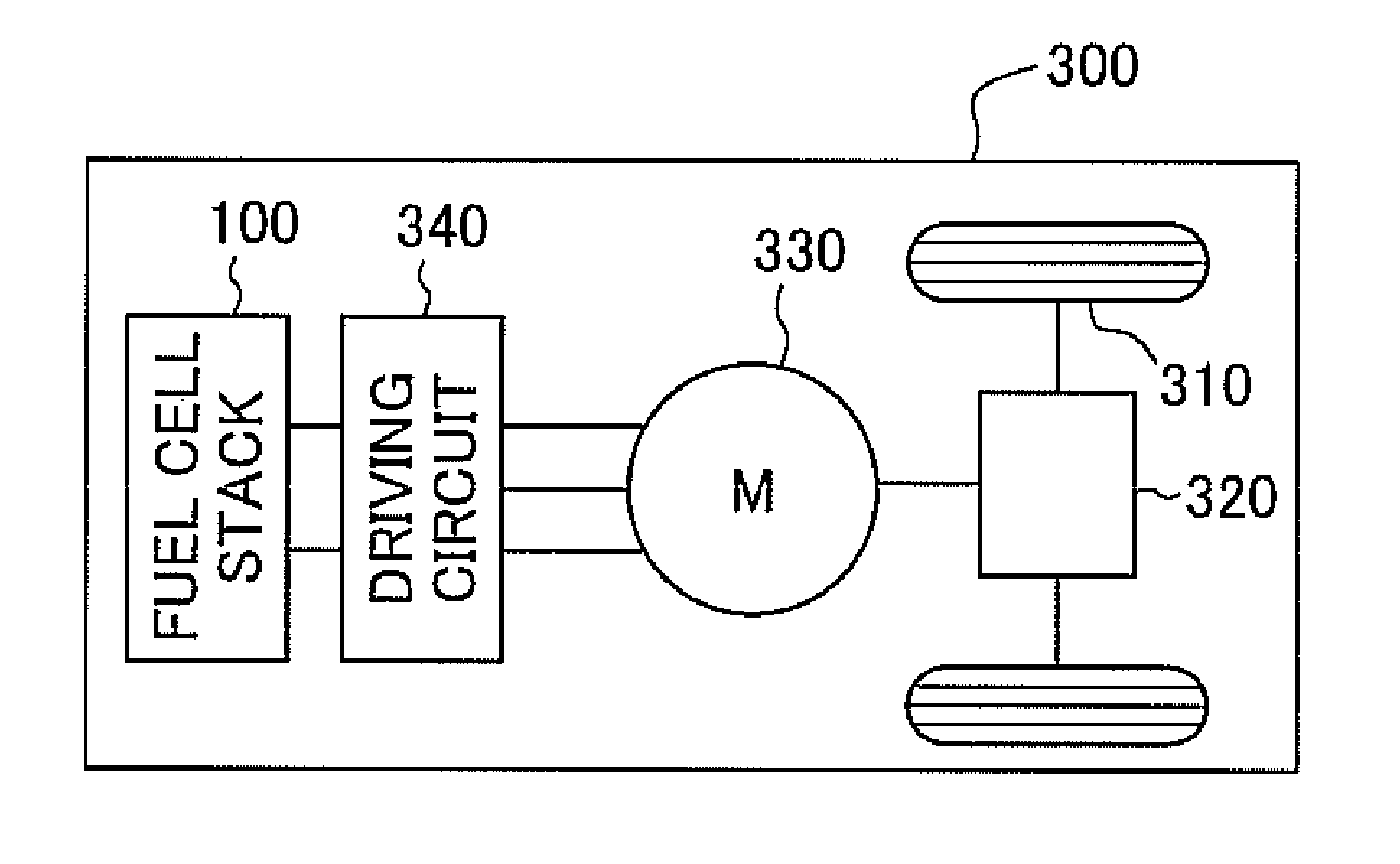
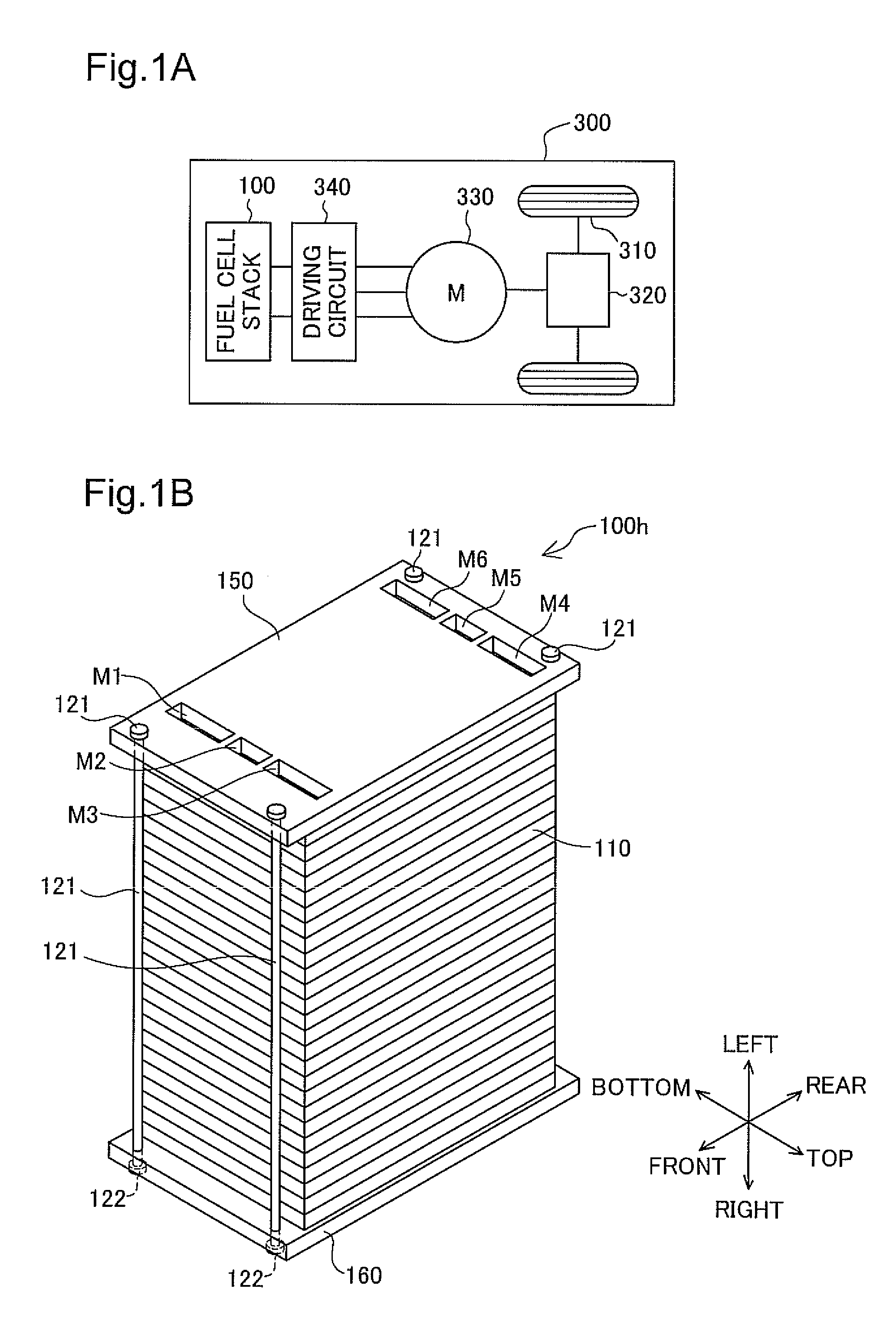
[0024]FIG. 1A is an explanatory view illustrating the configuration of a vehicle equipped with a fuel cell stack in one embodiment of the invention. As illustrated, a vehicle 300 includes a fuel cell stack 100, a motor 330 as a drive source of the vehicle 300, and a driving circuit 340 configured to consume electric power supplied from the fuel cell stack 100 and drive the motor 330. The power generated by the motor 330 is transmitted via a gear box 320 to a pair of drive wheels 310. The motor 330 is a three-phase motor with permanent magnets. The driving circuit 340 uses switching elements (not shown) to convert the direct-current power obtained from the fuel cell stack 100 into three-phase alternating-current driving power and supplies the three-phase alternating-current driving power to the motor 330.

[0025]The fuel cell stack 100 is described below. FIG. 1B is an explanatory view showing the fuel cell stack 100 o...

second embodiment

B. Structure of Fuel Cell Stack in Second Embodiment of the Invention

[0040]FIG. 5 is an exploded view illustrating a fuel cell stack 100a in a second embodiment of the invention. The difference of the fuel cell stack 100a of the second embodiment from the fuel cell stack 100 of the first embodiment is that four studs 121a given as fastener members for fastening end plates 150a and 160a located across a cell laminate 110a are joined and structurally integrated with displacement preventing members 200a (discussed later). For the clarity of explanation, the displacement preventing members 200a are omitted from the illustration of FIG. 5. The coordinate system of FIG. 5 defines directions of the fuel cell stack 100a mounted in a certain orientation on a vehicle (not shown).

[0041]The end plates 150a and 160a are located on both ends of the cell laminate 110a in its stacking direction and fastened to the cell laminate 110a with the four studs 121a and eight bolts 122a. The motions of the ...


PUM


Abstract

A fuel cell stack in accordance with the invention has a cell laminate obtained by stacking multiple plates with at least one of functions of a power generation assembly and a separator, and a pair of end plates located outside and on both ends of the cell laminate in a stacking direction. The fuel cell stack further includes a displacement preventing member extended along the stacking direction of the cell laminate and fastened to the pair of end plates, and a deformable intermediate material located between the cell laminate and the displacement preventing member over an area of two or more plates among the multiple plates. At least either one of the two or more plates and the displacement preventing member is designed to have a concavo-convex shape formed at least partially on a face in contact with the intermediate material. Such a simple structure of the fuel cell stack effectively enhances the resistance against an inertial force acting in an in-plane direction that is perpendicular to the stacking direction.

Description

TECHNICAL FIELD[0001]The present invention relates to a fuel cell stack.BACKGROUND ART[0002]One prior art structure of a fuel cell stack mountable on a vehicle has a cell laminate obtained by alternately stacking plates with the function of a power generation assembly and plates with the function of a separator. The fuel cell stack of this prior art structure has a problem of low resistance against an inertial load in a direction (may be referred to as ‘in-plane direction’ in the description herein) perpendicular to a stacking direction of the respective plates (may be simply referred to as ‘stacking direction’ in the description herein). Each plate generates a drag in a plane-pressing direction against an inertial load in the stacking direction, while generating a drag from a frictional force acting on an interface between each adjacent pair of plates against the inertial load in the in-plane direction. One proposed structure as disclosed in JP-A-2006-108009 forms a recess along th...

Claims


Application Information

Patent Timeline
IPC IPC(8): B60L11/18H01M2/00
CPCH01M8/247H01M8/2475Y02E60/50H01M2250/20Y02T90/32H01M8/248Y02T90/40
Inventor SAITO, NORIHIKO
Owner TOYOTA JIDOSHA KK
Why Eureka
Try Eureka