Motor brake

a technology of motor brakes and brake pads, applied in the direction of mechanical equipment, mechanical energy handling, transportation and packaging, etc., can solve the problems of braking error, force applied to the brake panel, and against the brake lining, so as to achieve accurate control of the rotation and stoppage of the motor, rapid reaction speed, and durable use

Inactive Publication Date: 2010-06-03
WEI TA CHUEN
View PDF5 Cites 3 Cited by
  • Summary
  • Abstract
  • Description
  • Claims
  • Application Information

AI Technical Summary

Benefits of technology

[0008]The present invention has been accomplished under the circumstances in view. It is therefore the main object of the present invention to provide motor brake, which has a rapid reaction speed to control rotation and stoppage of the motor accurately. It is another object of the present invention to provide a motor brake, which is durable in use, avoiding damage to the parts upon a braking action.

Problems solved by technology

1. Only one single winding 13 is provided to produce a magnetic attractive force for attracting the brake lining 16, the reaction speed in controlling rotation or stoppage of the shaft 19 of the motor 18 is low, and a braking error may occur.
2. Because of low magnetic attractive force, the spring force of the spring members 15 is limited, thus the force applied to the brake panel 14 against the brake lining 16 is limited, and the shaft 19 of the motor 18 may be not stopped accurately when braking.
3. During a braking action, the outer panel 17 receives a great torsional force from the braking lining 16, and therefore the screws 41 wear quickly with use.

Method used


Image

  • Motor brake
  • Motor brake
  • Motor brake

Examples


Embodiment Construction

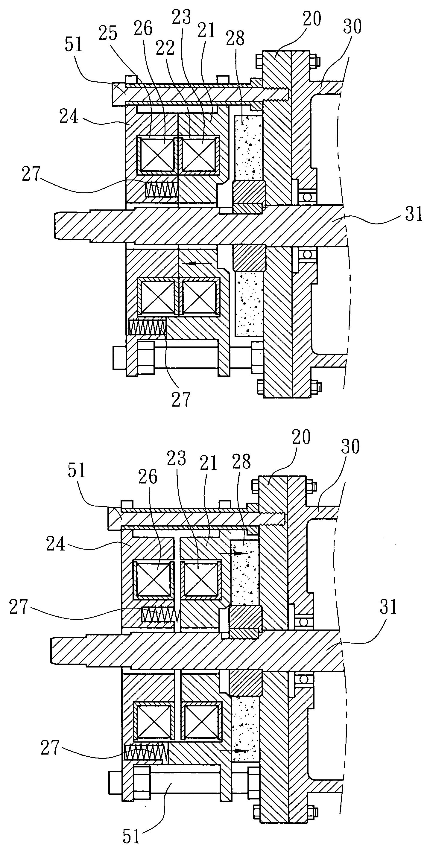
[0018]Referring to FIGS. 4˜6, a motor brake in accordance with the present invention is shown comprising a locating plate 20 affixed to one side of a motor 30 around a shaft 31 of the motor 30, an outer panel 24 connected to the locating plate 20 with screws 51, a brake lining 28 affixed to one side of the locating plate 30 around the shaft 31 of the motor 30, an inner panel 21 movable along the screws 51 between the brake lining 28 and the outer panel 24, a plurality of spring members 27 connected between the inner panel 21 and the outer panel 24 to force the inner panel 21 against the brake lining 28, a first winding 23 mounted in an annular groove 22 in one side of the inner panel 21 and facing the outer panel 24, and a second winding 26 mounted in an annular groove 25 in one side of the outer panel 24 and facing the first winding 23. Further, the inner panel 21 has two locating notches 210 on its one side. The outer panel 24 has two locating blocks 240 for engaging into the loca...


PUM


Abstract

A motor brake includes a locating plate affixed to a motor around the motor shaft, an outer panel connected to the locating plate with screws, a brake lining affixed to the locating plate, an inner panel movable along the screws between the brake lining and the outer panel, spring members connected between the inner panel and the outer panel for forcing the inner panel against the brake lining to stop the shaft of the motor from rotation, and two windings respectively mounted in the inner panel and the outer panel for attracting each other to move the inner panel away from the brake lining for allowing rotation of the motor shaft when electrically connected.

Description

BACKGROUND OF THE INVENTION[0001]1. Field of the Invention[0002]The present invention relates to a motor brake for motor and more particularly to such a motor brake, which is durable in use and, which accurately performs the braking action.[0003]2. Description of the Related Art[0004]FIGS. 1˜3 show a motor brake according to the prior art. According to this design, the motor brake comprises a locating plate 10 affixed to one side of a motor 18, an inner panel 11 mounted on one side of the locating plate 10 around the shaft 19 of the motor 18, a winding 13 mounted in an annular groove 12 in the inner panel 11, an outer panel 17 connected to the inner panel 11 with screws 41, a brake panel 14 movable along the screws 41 between the inner panel 11 and the outer panel 17, a brake lining 16 mounted on the shaft 19 of the motor 18 between the brake panel 14 and the outer panel 17, and spring members 15 supported between the inner panel 11 and the brake panel 14. When the winding 13 is ele...

Claims


Application Information

Patent Timeline
Patent Type & Authority Applications(United States)
IPC IPC(8): B60L7/00
CPCH02K7/1025F16D2121/22
Inventor WEI, TA-CHUEN
Owner WEI TA CHUEN
Why Eureka
Try Eureka