Al technical title is built by PatSnap Al team. It summarizes the technical point description of the patent document.
a cap assembly and removable technology, applied in the field of removable cap assembly, can solve the problems of loosened stopper, easy loosening of the stopper, and simple friction between the stopper and the bottle, and achieve the effect of easy attachment and removal
Inactive Publication Date: 2010-06-03
VER HAGE RICHARD P
View PDF12 Cites 4 Cited by
Summary
Abstract
Description
Claims
Application Information
AI Technical Summary
This helps you quickly interpret patents by identifying the three key elements:
Problems solved by technology
Method used
Benefits of technology
[0014]It is another object of the present invention to provide an improved removable cap assembly that can be easily attached to and detached from a standard threaded bottle.
[0015]It is still another object of the present invention to provide an improved removable cap assembly that provides a relatively rigid support for a sipper tube.
[0016]It is yet another object of the present invention to provide an improved removable cap assembly that has multiple thread starts for use in conjunction with threaded bottle.
Problems solved by technology
The use of a simple friction fit between the stopper and the bottle has at least one major limitation.
Because the bottle is inverted, the weight of the liquid tends to loosen the stopper.
Furthermore, the stopper is loosened by vibrations and motion caused by an animal using the bottle.
These loosening effects may eventually cause the stopper to come apart from the bottle, allowing liquid to escape.
However, this action may cause health problems, such carpal tunnel syndrome, for a person who must repetitively insert stoppers into bottles.
While the device described in this patent helps to solve some problems inherent in prior art, at least one major limitation is intrinsic in its design.
Thus, the problem remains that the sipper tube can be wriggled, allowing leakage of the bottle contents or the removal of the sipper tube.
The lip tends to collect dirt and germs which can be harmful to the animals or those handling the bottle assemblies.
Another problem with this prior art device is manner in which the seal is crated after the cap is turned 180 degrees.
Specifically, these limitations include the rigidity and security with which the sipper tube is held by a stopper in the bottle.
Additionally, problems with regard to cleanliness stem from design features in the prior art.
Method used
Image
Click on the blue label to locate the original text in one second.
Reading with bidirectional positioning of images and text.
Examples
Embodiment Construction
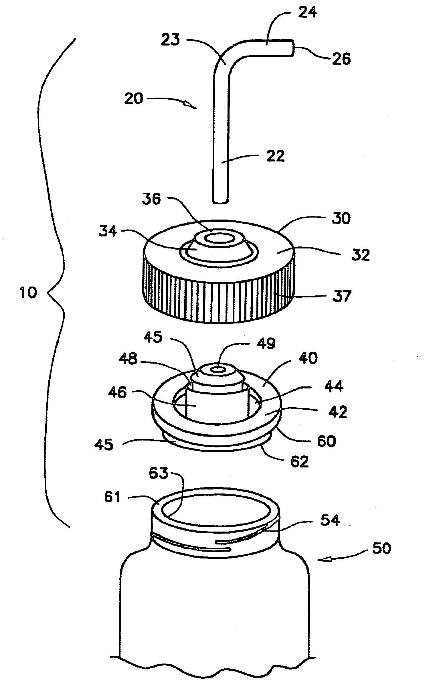
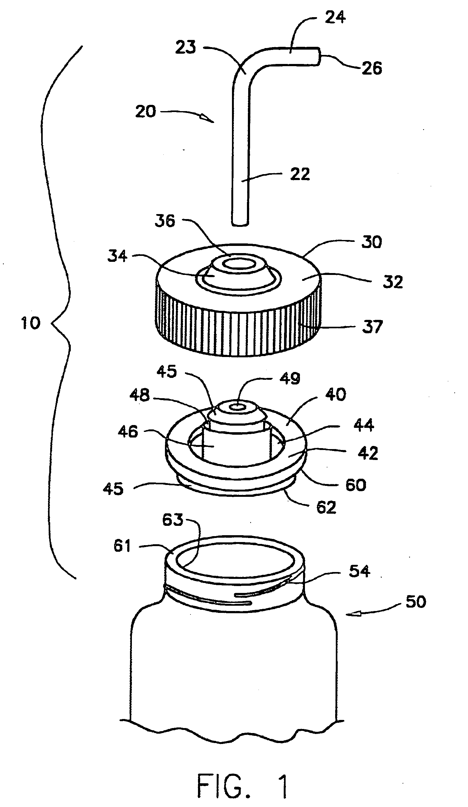
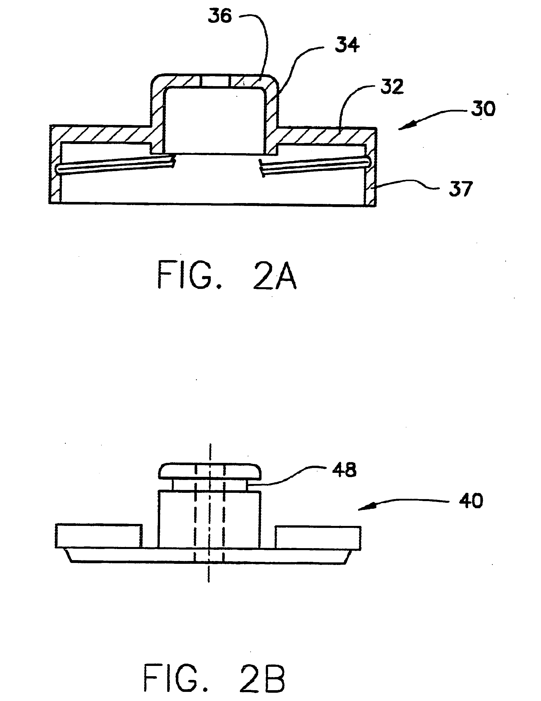
[0034]In accordance with one embodiment, the present invention is directed to a removable cap assembly 10. The salient features of the present invention, according to one embodiment, are shown in FIG. 1. Although not limited thereto, assembly 10 includes a sipper tube 20, a cap 30, and a stopper 40 that, together, can be coupled to a bottle mouth 50. The stopper fits in the cap to help provide a water tight sealing device for covering mouth 50. Tube 20 is then held by stopper 40 to provide an animal feeding bottle.
[0035]Sipper 20 can be one of many commercially available and well-known tube shaped devices that are designed to dispense small amounts of liquid on demand. The simplest of these devices, shown in FIG. 1, includes a vertical portion 22 and an angled portion 24 that is bent about an elbow 23. Tube 20 has a hole 26 at its end. The hole is dimensioned so that a relatively small amount of liquid can flow when the liquid's surface tension is broken. It is understood that many ...
PUM
Property
Measurement
Unit
width
aaaaa
aaaaa
height
aaaaa
aaaaa
shape
aaaaa
aaaaa
Abstract
A removable cap assembly has a cap with a curved side wall having an inner surface and an outer surface, a top portion extending from the curved side wall, a boss extending perpendicularly from the top portion, with the boss having a bottom and a top. A first circumferential rib extends perpendicularly from the top of the boss, with the boss and rib defining an opening in the cap. A stopper is dimensioned to seal the opening having a shape complementary to the boss and a hole therein configured to allow a fluid to flow therethrough. The stopper is maintained in the cap by the shape of the boss and includes a disc shaped base, a cylindrical wall portion extending from the base, a first groove in the base surrounding the wall portion, the first groove dimensioned to receive the bottom of the boss.
Description
RELATED APPLICATIONS[0001]This application is a continuation application U.S. patent application Ser. No. 11 / 636,368. filed on Dec. 8, 2006, which is a divisional application of U.S. patent application Ser. No. 10 / 848,455, filed on May 17, 2004, now U.S. Pat. No. 7,156,264 which is a divisional application of U.S. patent application Ser. No. 10 / 302,733, filed on Nov. 22, 2002, now U.S. Pat. No. 6,786,179, which in turn is a divisional application of U.S. patent application Ser. No. 09 / 652,737, filed on Aug. 31, 2000, now issued as U.S. Pat. No. 6,684,814, the entirety of which are incorporated herein by reference.BACKGROUND[0002]1. Field of the Invention[0003]This invention relates to an improved removable cap assembly for an animal feeding bottle.[0004]2. Description of Related Art[0005]Small rodents such as mice, rats, guinea pigs, and hamsters are used in scientific research and they are sometimes kept as pets by children. Typically, such animals are held in small cages where the...
Claims
Application Information
Patent Timeline
Application Date:The date an application was filed.
Publication Date:The date a patent or application was officially published.
First Publication Date:The earliest publication date of a patent with the same application number.
Issue Date:Publication date of the patent grant document.
PCT Entry Date:The Entry date of PCT National Phase.
Estimated Expiry Date:The statutory expiry date of a patent right according to the Patent Law, and it is the longest term of protection that the patent right can achieve without the termination of the patent right due to other reasons(Term extension factor has been taken into account ).
Invalid Date:Actual expiry date is based on effective date or publication date of legal transaction data of invalid patent.
Patent Type & Authority Applications(United States)