Electrodeless lamps with grounded coupling elements and improved bulb assemblies

a technology of coupling elements and electric lamps, which is applied in the direction of energy-saving lighting, structural circuit elements, sustainable buildings, etc., can solve the problems of limited lifetime, deterioration of electrodes, and other limitations of conventional plasma lamps, so as to reduce costs, reduce costs, and improve efficiency

Inactive Publication Date: 2010-06-03
TOPANGA USA
View PDF23 Cites 11 Cited by
  • Summary
  • Abstract
  • Description
  • Claims
  • Application Information

AI Technical Summary

Benefits of technology

[0021]One or more benefits may be achieved using the present lamp and related methods. As an example, the present lamp is compact and can be configured inside conventional luminaires, such as luminaires used for street lighting and parking lot lighting, among other applications. Furthermore, the present lamp can be configured to have an exposed arc to allow use of conventional optical components, such as aluminum reflectors, diffusers, and other components, alone or in combination. In one or more embodiments, the present lamp can also be manufactured more efficiently and at lower costs than the conventional dielectric resonators, such as those described in U.S. Pat. No. 6,737,809B2. That is, the compact air resonator / waveguide is significantly lower cost and simpler to manufacture since it does not require a dielectric material (alumina) or other materials. Also by eliminating the RF losses associated with the dielectric material, the performance of the lamp improves. Furthermore, the lamp can be configured to have an exposed arc to allow use of conventional optical components. These and other benefits may be achieved in one or more embodiments. Further details of the present invention can be found throughout the present specification and more particularly below.

Problems solved by technology

This arrangement, however, suffers from deterioration of the electrodes inside the bulb, and therefore a limited lifetime.
Other limitations also exist with conventional plasma lamps.

Method used


Image

  • Electrodeless lamps with grounded coupling elements and improved bulb assemblies
  • Electrodeless lamps with grounded coupling elements and improved bulb assemblies
  • Electrodeless lamps with grounded coupling elements and improved bulb assemblies

Examples


Embodiment Construction

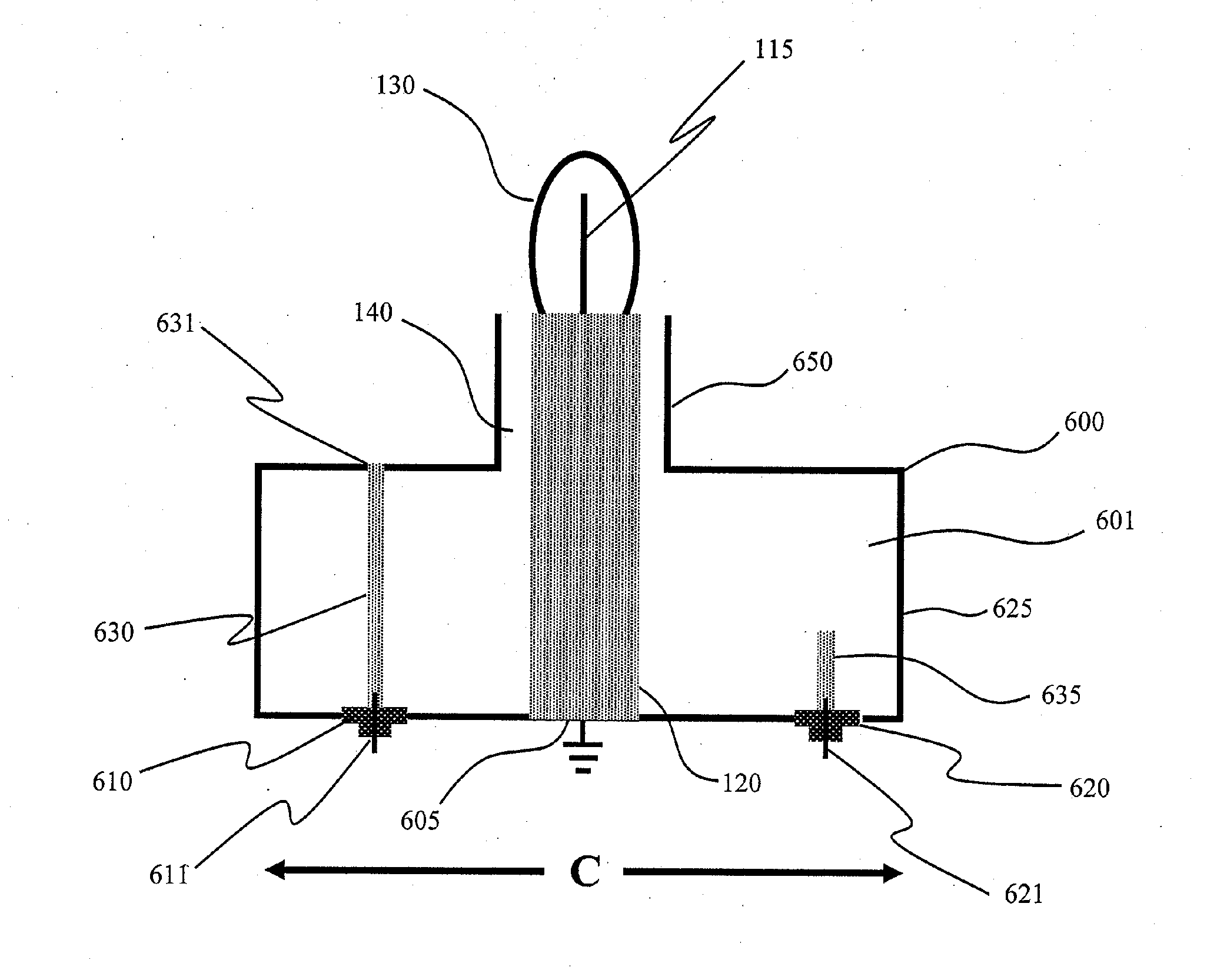
[0044]According to the present invention, techniques directed to devices and methods for generating light with plasma lamps are provided. More particularly, the present invention provides plasma lamps driven by a radio-frequency source without the use of electrodes inside a gas-filled vessel (bulb) and related methods. Merely by way of example, such plasma lamps can be applied to applications such as stadiums, security, parking lots, military and defense, street lighting, large and small buildings, bridges, warehouses, agriculture, uv water treatment, architectural lighting, stage lighting, medical illumination, microscopes, projectors and displays, any combination of these, and the like.

[0045]The following description is presented to enable one of ordinary skill in the art to make and use the invention and to incorporate it in the context of particular applications. Various modifications, as well as a variety of uses in different applications will be readily apparent to those skill...


PUM


Abstract

An electrode-less plasma lamp, comprising generally of a bulb containing a gas-fill and light emitter(s) that is excited to produce light using radio-frequency (RF) energy. The present lamp includes compact air resonators/waveguides that use grounded coupling-elements with integrated bulb assemblies to reduce the size of the resonator and improve the performance of the lamp as well as reduce cost and simplify manufacturability.

Description

CROSS-REFERENCE TO RELATED APPLICATION[0001]This application is a continuation in part and also claims priority to U.S. application Ser. No. 12 / 484,933, filed Jun. 15, 2009, which claims priority to U.S. Provisional Ser. No. 61 / 075,735 filed Jun. 25, 2008, all commonly assigned, and hereby incorporated by reference for all purposes.BACKGROUND OF THE INVENTION[0002]The present invention is directed to devices and methods for generating light with plasma lamps. More particularly, the present invention provides plasma lamps driven by a radio-frequency source without the use of electrodes inside the bulb and related methods. Merely by way of example, such plasma lamps can be applied to applications such as stadiums, security, parking lots, military and defense, street lighting, large and small buildings, vehicle headlamps, aircraft landing, bridges, warehouses, uv water treatment, agriculture, architectural lighting, stage lighting, medical illumination, microscopes, projectors and disp...

Claims


Application Information

Patent Timeline
Patent Type & Authority Applications(United States)
IPC IPC(8): H01J7/46H01J61/00H05B41/24
CPCH01J65/046Y02B20/22H05B41/2806H01J65/048Y02B20/00
Inventor ESPIAU, FREDERICK M.BROCKETT, TIMOTHY J.MATLOUBIAN, MEHRANDOUGHTY, DOUGLAS A.
Owner TOPANGA USA
Why Eureka
Try Eureka