Electromagnetic wave measuring apparatus

Inactive Publication Date: 2010-06-03
SONY CORP
View PDF2 Cites 10 Cited by
  • Summary
  • Abstract
  • Description
  • Claims
  • Application Information

AI Technical Summary

Benefits of technology

[0019]1. Use of a metallic substance for an antenna positioner is avoided to a maximum extent, thus avoiding electrical interference to a reception antenna;
[0020]2. A coaxial cable connected to the reception antenna is placed with a separation distance of at least 1 m or more, thus avoiding electrical interference to the reception antenna; and
[0024]Moreover, each of the antenna positioners in related art shown in FIGS. 19A to 19C has the center of gravity relatively high with respect to the floor, which lacks stability. Further, when a position of the reception antenna is set high, the antenna mast is liable to swing due to its own weight, which also lacks stability. Furthermore, many metal portions are exposed from the antenna positioner, a distance between the antenna positioner and the reception antenna is small, and an electromagnetic wave is caused between the antenna positioner and the floor made of metal. As a result, there is generated EMI other than an electromagnetic wave that is generated by the electronic apparatus as a measurement target, and the reception antenna receives the EMI, thus reducing accuracy of the EMI measurement of the electronic apparatus.
[0026]In view of the circumstances as described above, it is desirable to prevent an electromagnetic wave generated by an electromagnetic wave measuring apparatus itself from affecting an EMI measurement when the EMI measurement of an electronic apparatus is performed.
[0031]With this structure, by the base portion that is capacitively coupled to the floor, an unnecessary electromagnetic wave such as EMI (approximately 30 to 300 MHz) generated from the power portion and the like is prevented from being radiated.
[0032]According to the embodiment of the present invention, by appropriately shielding circumferences of the power portion and the like included in the electromagnetic wave measuring apparatus, it is possible to perform the EMI measurement of the electronic apparatus while suppressing influence of the electromagnetic wave generated by the electromagnetic wave measuring apparatus itself. In this case, a thickness of the base portion is considered to be the same as an asperity tolerance range with respect to the floor, the asperity tolerance range being provided by the standards, because a gap between the floor and the flat bottom surface opposed to the floor is set to 2 mm or less. Further, the mast-fixing portion is formed to have a height of 45 mm or less vertical to the floor and is considered to be the same as the floor, with the result that there is an effect that the EMI measurement of the electronic apparatus is not affected.

Problems solved by technology

In addition, since recent technologies in digital electronic apparatuses are diversified, fundamental waves and harmonics of a plurality of clock signals or digital transmission signals synchronized therewith tend to be superimposed complicatedly.
Therefore, it has been difficult to identify a generation source of EMI and a transmission path.
On the other hand, in terms of an EMI evaluation facility, an EMI evaluation error is caused due to electrical interference (capacitive coupling, electromagnetic wave reflection, or EMI radiated by drive portion, its driver, and controller portion) with respect to a reception antenna of an antenna positioner used in the EMI evaluation facility.
When the electrical interference is added, antenna characteristics (directivity, impedance, and the like) may be changed, resulting in a factor of the EMI evaluation error of the electronic apparatus.
However, since a degree of electrical interference cannot be derived easily, the documents include qualitative descriptions.

Method used


Image

  • Electromagnetic wave measuring apparatus
  • Electromagnetic wave measuring apparatus
  • Electromagnetic wave measuring apparatus

Examples


first embodiment

(1. First Embodiment)

[0058](Use Example and Structure Example of Antenna Positioner)

[0059]First, a first embodiment of the present invention will be described with reference to FIGS. 1 to 15.

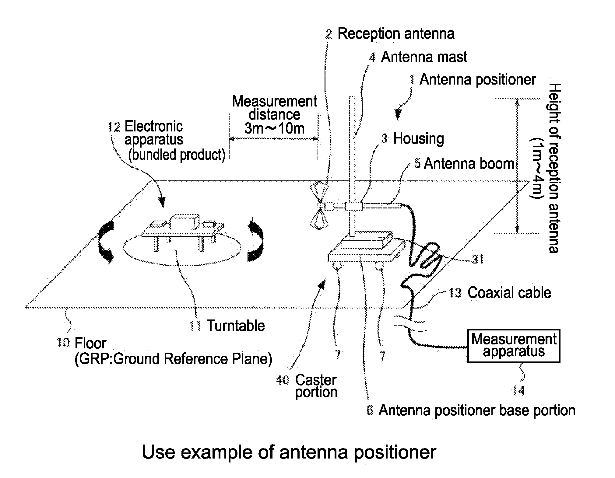
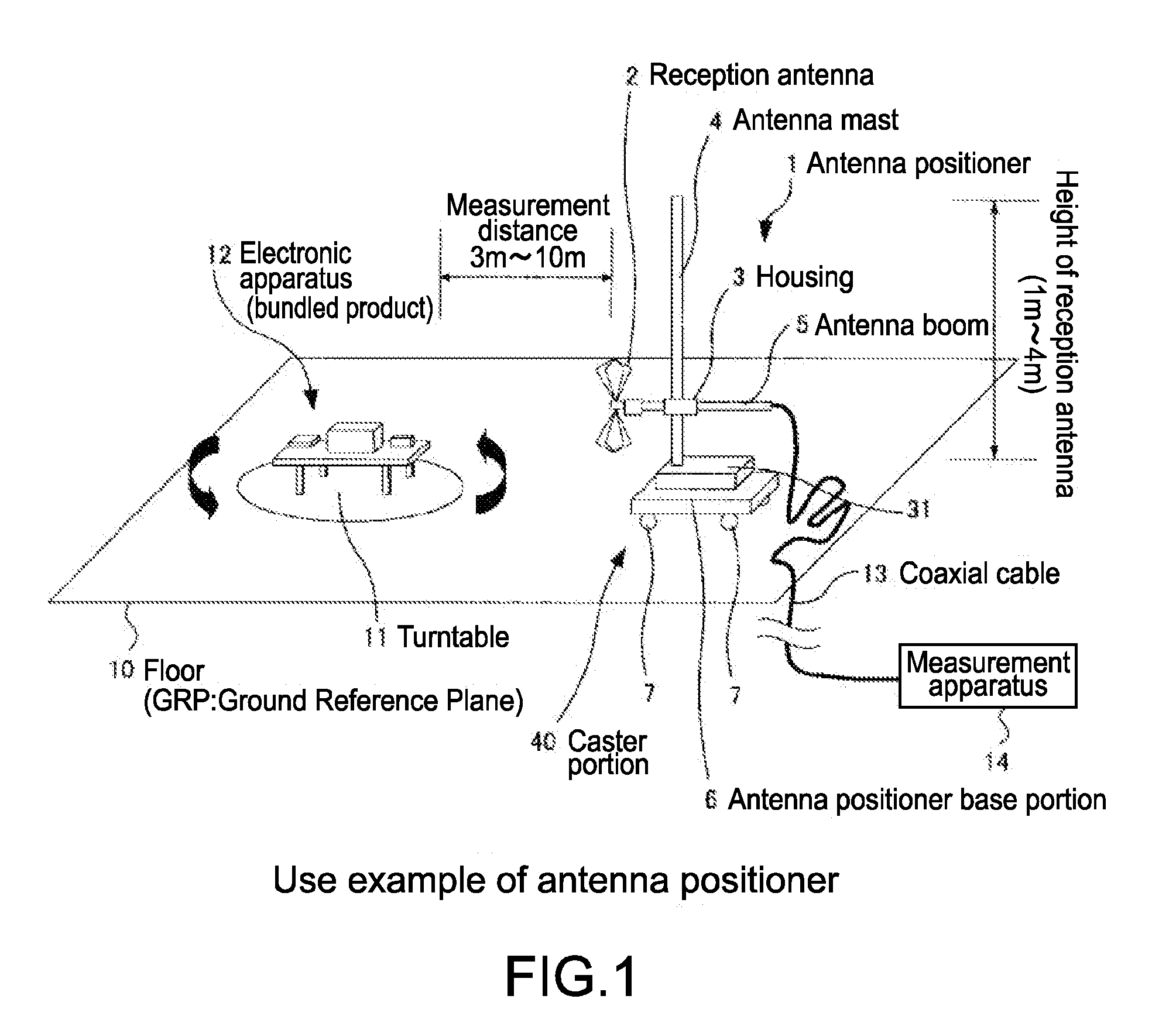
[0060]In this embodiment, there will be described an example in which the present invention is applied to an antenna positioner 1 as an electromagnetic wave measuring apparatus for measuring electro-magnetic interference (EMI) radiated from an electronic apparatus (bundled product) and the like. In this example, the electronic apparatus that is subjected to an EMI measurement and the antenna positioner 1 are placed within an EMI evaluation facility.

[0061]FIG. 1 shows a use example of the antenna positioner 1 of this example.

[0062]The antenna positioner 1 placed on a floor 10 called GRP includes a reception antenna 2 that measures an electromagnetic wave generated by an electronic apparatus 12 and an antenna mast 4 that holds the reception antenna 2 so as to be movable in a vertical direction. Th...

second embodiment

(2. Second Embodiment)

[0178](Thinning of Antenna Positioner Base Portion and Lowering of Center of Gravity Thereof)

[0179]Next, a second embodiment of the present invention will be described with reference to FIG. 16. In the following description, portions corresponding to the figures that has been described in first embodiment are denoted by the same reference numerals and detailed descriptions thereof will be omitted.

[0180]In this embodiment, there is examined a case where, when the flatness of the floor 10 near the position where the antenna positioner 1 is placed is insufficient, the separation distance therebetween is above 2 mm (for example, 5 mm). In this case, in accordance with a frequency band of EMI generated in the controller 23 and the power portion 25 such as a servo motor, a dielectric material having a largest dielectric constant in the frequency band is placed on a lower portion of the bottom surface of the antenna positioner base portion 6. At this time, a thickness...

third embodiment

(3. Third Embodiment)

[0185](EMI Suppression From Power Portion, Power Control Portion, and Controller)

[0186]Next, a third embodiment of the present invention will be described with reference to FIGS. 17 and 18. In the following description, portions corresponding to the figures that has been described in first embodiment are denoted by the same reference numerals and detailed descriptions thereof will be omitted.

[0187]FIG. 17 shows an external structure example of an antenna positioner base portion 80 when viewed from above.

[0188]A basic structure of the antenna positioner base portion 80 is similar to that of the antenna positioner base portion 6 described in the first embodiment above. The antenna positioner base portion 80 in this embodiment includes a frame 82 that reinforces a bottom surface steel plate 81 whose thickness is thin. By the frame 82, the strength of the antenna positioner base portion 80 is maintained and distortion deformation can be prevented. Further, the inter...


PUM


Abstract

An electromagnetic wave measuring apparatus includes: a reception antenna receiving an electromagnetic wave generated from an electronic apparatus placed at a predetermined distance away; an antenna mast holding the reception antenna; and a base portion fixing an end of the antenna mast vertically to a floor, the base portion having a flat bottom surface opposed to the floor, the bottom surface and the floor forming a gap of 2 mm or less therebetween and being capacitively coupled to each other. The base portion includes a mast-fixing portion having a height of 45 mm or less vertically to the floor and fixing the end of the antenna mast, a power portion being disposed at a position away from the reception antenna and generating power, and a power transmission portion transmitting the power generated by the power portion to the reception antenna and vertically moving the reception antenna along the antenna mast.

Description

BACKGROUND OF THE INVENTION[0001]1. Field of the Invention[0002]The present invention relates to an electromagnetic wave measuring apparatus that is suitably applicable to, for example, a case of measuring EMI (Electromagnetic Interference) radiated from an electronic apparatus or the like.[0003]2. Description of the Related Art[0004]From the past, electromagnetic waves radiated from a clock oscillation circuit and the like included in many electronic apparatuses (for example, bundled products such as computer apparatus and recorder), for driving a CPU, a bus, an external memory, and the like, may become a cause of electromagnetic interference (EMI) that disturbs functions of other electronic apparatuses. Therefore, public institutions such as International Special Committee on Radio Interference and American National Standards Institute have established EMI industry standards. Further, government institutions such as Federal Communications Commission (hereinafter, abbreviated as FC...

Claims


Application Information

Patent Timeline
IPC IPC(8): G01R29/08H01Q3/00
CPCG01R29/0878G01R29/0871
Inventor OKAZAKI, MASAHIRO
Owner SONY CORP
Why Eureka
Try Eureka