
Liquid Crystal Display and Method of Driving the Same

a technology of liquid crystal display and liquid crystal, applied in the direction of non-linear optics, static indicating devices, instruments, etc., can solve the problems of deterioration of display quality, rapid charge and discharge, and possibly vibrating, so as to reduce audible noise and improve display quality

Inactive Publication Date: 2010-06-03
SAMSUNG ELECTRONICS CO LTD
View PDF4 Cites 23 Cited by
  • Summary
  • Abstract
  • Description
  • Claims
  • Application Information

AI Technical Summary

Benefits of technology

The present invention provides an LCD that can improve display quality and reduce audible noise. This is achieved by providing a first data signal to the display panel during a first frame period, providing a second data signal to the display panel during a second frame period, and providing a blank signal to the display panel during a blank period between the first and second frame periods. The voltage of the blank signal is varied among a plurality of levels between the voltage of the first data signal and the voltage of the second data signal. This results in a more stable display and reduced noise.

Problems solved by technology

Due to an increasing size of LCDs and an increasing signal frequency transmitted by LCDs, a rapid change in the data voltage polarity may result in an insufficient time to charge the liquid crystal capacitors with a target voltage, which may cause a deterioration of display quality.
In addition, if a data voltage applied to each pixel rapidly changes, a current through each data line may also rapidly change, causing a multi-capacitor for generating a driving voltage to quickly charge and discharge and possibly vibrate due to a piezo effect.
When the multi-capacitor vibrates, a printed circuit board (PCB) on which the multi-capacitor is mounted may also vibrate, thereby causing audible noise.

Method used


Image

  • Liquid Crystal Display and Method of Driving the Same
  • Liquid Crystal Display and Method of Driving the Same
  • Liquid Crystal Display and Method of Driving the Same

Examples


Embodiment Construction

[0021]Embodiments of the present invention will now be described more fully with reference to the accompanying drawings, in which exemplary embodiments of the invention are shown. The invention may, however, be embodied in many different forms and should not be construed as being limited to the embodiments set forth herein. It will be understood that when an element is referred to as being “connected” or “coupled” to another element, it can be directly connected or coupled to the other element or intervening elements may be present. Like numbers refer to like elements throughout.

[0022]A liquid crystal display (LCD) and a method of driving the LCD, according to exemplary embodiments of the present invention, will hereinafter be described in detail with reference to FIGS. 1 through 7.

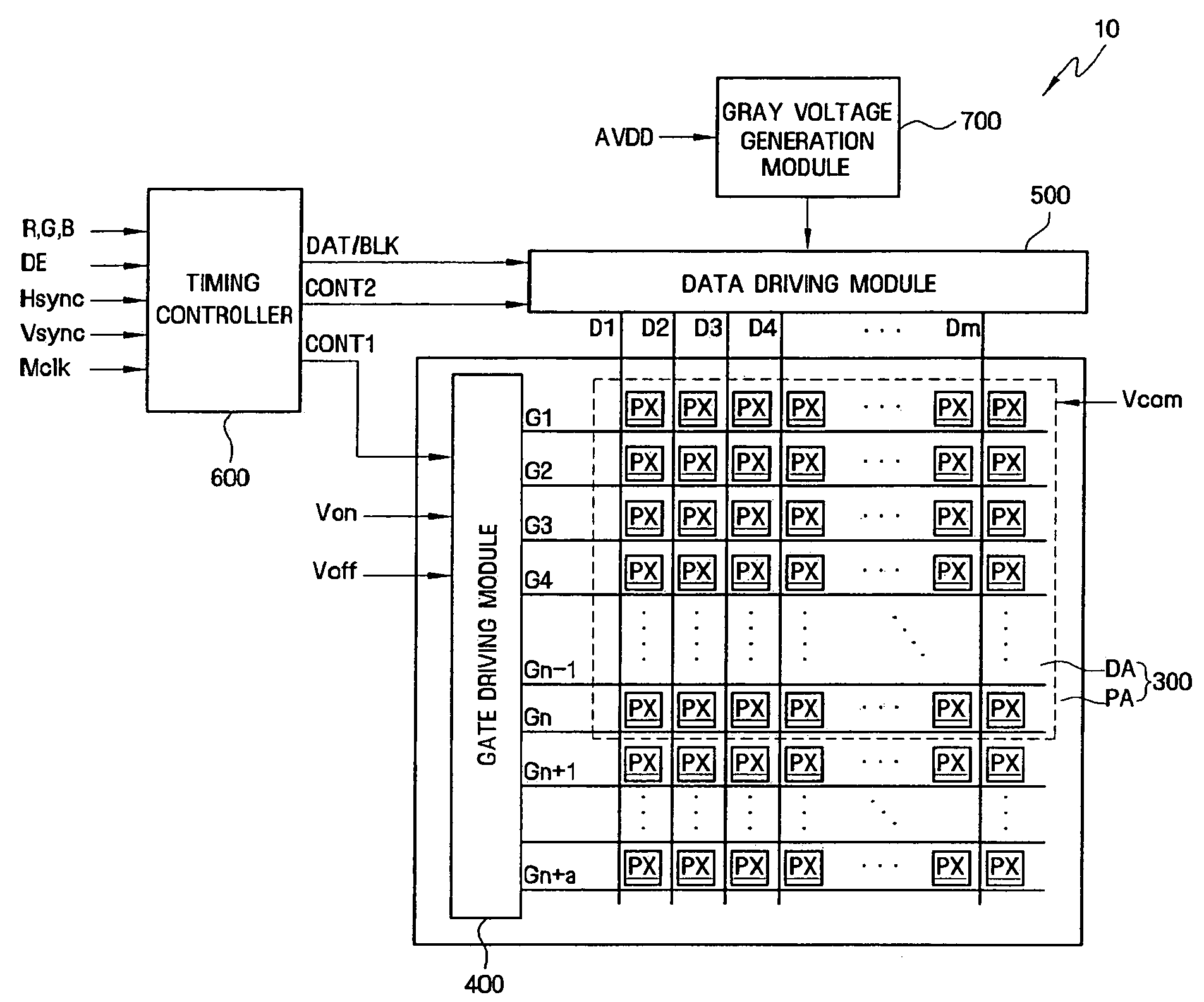
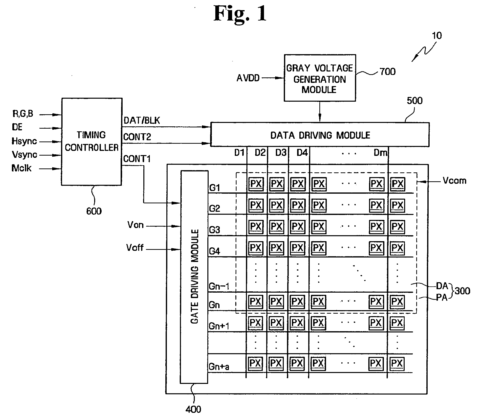
[0023]Referring to FIG. 1, an LCD 10 may include a display panel 300, a timing controller 600, a gate driving module 400, a data driving module 500, and a gray voltage generation module 700.

[0024]The disp...


PUM


Abstract

A liquid crystal display (LCD) and a method of driving the LCD are provided. The LCD includes a display panel; and a timing controller providing a first data signal to the display panel during a first frame period, a second data signal to the display panel during a second frame period and a blank signal to the display panel during a blank period between the first and second frame periods, wherein the voltage of the blank signal varies among a plurality of levels between the voltage of the first data signal and the voltage of the second data signal.

Description

CROSS-REFERENCE TO RELATED APPLICATION[0001]This application claims priority from Korean Patent Application No. 10-2008-0120518 filed on Dec. 1, 2008 in the Korean Intellectual Property Office, the contents of which are herein incorporated by reference in their entirety.BACKGROUND OF THE INVENTION[0002]1. Field of the Invention[0003]The present disclosure is directed to a liquid crystal display (LCD) and a method of driving the LCD, and more particularly, to an LCD and a method of driving the LCD, which can improve display quality and can reduce audible noise.[0004]2. Description of the Related Art[0005]Liquid crystal displays (LCDs) generally include a first display panel having a plurality of pixel electrodes, a second display panel having a common electrode, and a liquid crystal layer interposed between the first and second display panels and having dielectric anisotropy. The pixel electrodes are arranged in a matrix having a plurality of pixel electrode rows and a plurality of p...

Claims


Application Information

Patent Timeline
Patent Type & Authority Applications(United States)
IPC IPC(8): G09G3/36
CPCG09G3/3611G09G2310/0232G09G2310/0248G09G2340/16G09G2320/0209G09G2320/0252G09G2330/06G09G2310/066G09G3/36G02F1/133G09G3/20
Inventor SHIN, SEUNG-WOONKIM, YOUNG-KIIM, SUNG-WOONHWANG, JUN-HO
Owner SAMSUNG ELECTRONICS CO LTD
Learn More