
Objective replacement device for microscopes

a technology for replacing devices and microscopes, applied in the field of microscope objects, can solve problems that have not been satisfactorily solved, and achieve the effect of facilitating the change and shortest possible tim

Active Publication Date: 2010-06-03
CARL ZEISS MICROSCOPY GMBH
View PDF18 Cites 20 Cited by
  • Summary
  • Abstract
  • Description
  • Claims
  • Application Information

AI Technical Summary

Benefits of technology

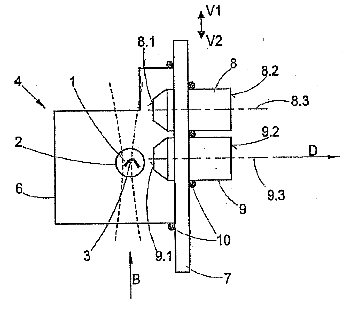
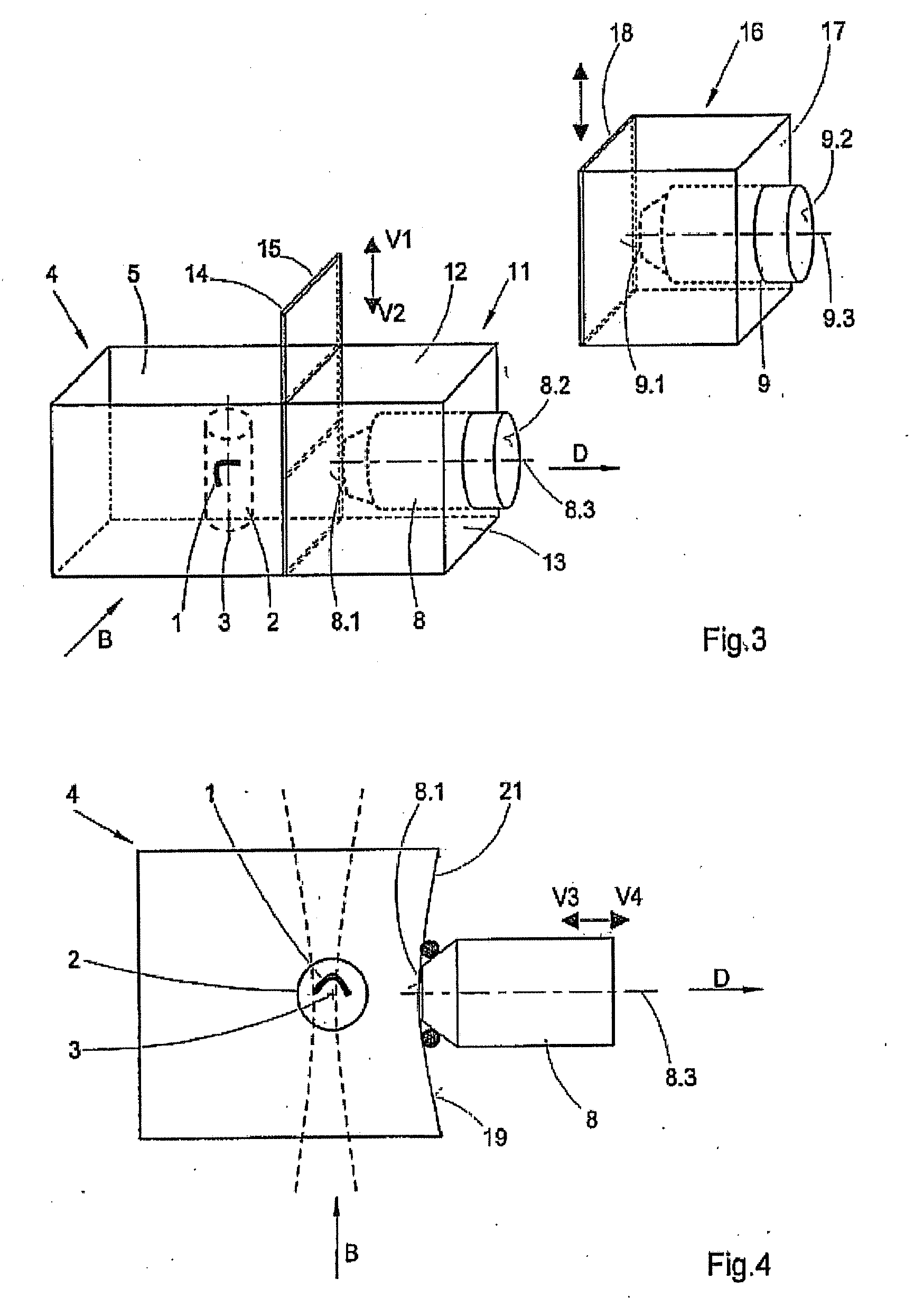
[0040]In this case, it is of special advantage if the specimen chamber wall is made of an elastic transparent material so that the lens that has been placed on this specimen chamber wall can be moved along the detection beam path, either toward the specimen or away from the specimen, and so that during this movement, contact between the first optically active surface and the specimen chamber wall is maintained.
[0041]With this movement, it is easily possible to vary the position of the focus in the specimen. Another advantage is that the lens can be easily removed from the specimen chamber wall and be replaced with a different lens having different optical properties, while the position and the orientation of the specimen remain unchanged. In addition, in the embodiment of the objective replacement device according to the present invention, both dry lenses and immersion lenses can be used.
[0043]It is conceivable and within the scope of the invention to insert a small hole in the elastic specimen chamber wall in the area of the axis of detection, through which hole the detection light is transmitted. The hole must be small enough that during the lens change, any leaking from the specimen chamber is prevented by the surface tension of the inversion [sic; immersion] medium and / or the reduced outflow time.
[0045]The above-described embodiments of the objective replacement device according to the present invention make it possible to easily and quickly change especially immersion lenses while the orientation of the specimen remains unchanged.

Problems solved by technology

A problem not yet satisfactorily solved in the prior art is how to change immersion lenses so as to be able to view a specimen, the position and orientation of which remains unchanged during the lens change, at different linear magnifications or different resolutions.

Method used


Image

  • Objective replacement device for microscopes
  • Objective replacement device for microscopes
  • Objective replacement device for microscopes

Examples


Embodiment Construction

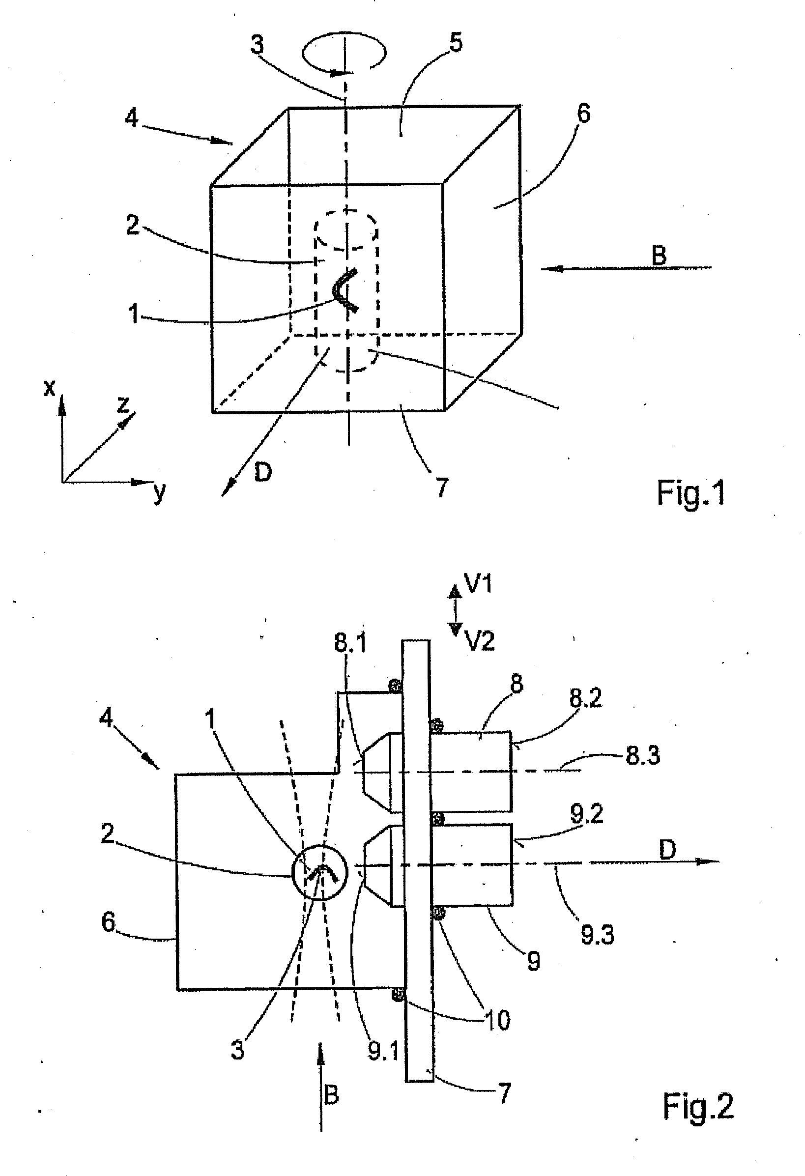
[0053]FIG. 1 illustrates the basic principle of single-plane illumination microscopy (SPIM). As FIG. 1 shows, a specimen 1 is embedded into a gel that has been formed into a circular cylinder 2. Let us assume that specimen 1 is a three-dimensional object, for example, a biological substance. Let us further assume that the gel is agarose.

[0054]The axis of rotation 3 of the circular cylinder 2 is oriented in the vertical direction, i.e., in the direction of action of the gravitational force. The circular cylinder 2 that encloses specimen 1 is located in a specimen chamber 4 which is filled with an immersion medium, for example, water. The specimen chamber 4 is open on the top side 5, by means of which not only specimen 1 that is surrounded by the gel, but also the immersion fluid, can be placed into the chamber.

[0055]Inside the specimen chamber 4, the circular cylinder 2, including specimen 1, can be subjected to a translatory movement in the coordinate directions X, Y, Z and is mount...


PUM


Abstract

The invention relates to an objective replacement device for a microscope, wherein the sample is located in a sample chamber and surrounded by an immersion medium within the sample chamber, means for positioning and aligning the sample relative to the focus of an objective being present, wherein the detection beam path is aligned horizontally, which is to say perpendicular to the direction of action of gravity. For an objective replacement device for a microscope of the type described above, according to the invention a device is provided for exchanging the objective, at the focus of which the sample is positioned and aligned, with at least another objective, the position and alignment of the sample within the sample chamber remaining the same.

Description

RELATED APPLICATIONS[0001]The present application is a U.S. National Stage application of International PCT Application No. PCT / EP2008 / 002680 filed on Apr. 4, 2008 which claims priority benefit of German Application No. DE 10 2007 018 862.7 filed on Apr. 18, 2007, the contents of each are incorporated by reference in their entirety.FIELD OF THE INVENTION[0002]The present invention relates to an objective replacement device for a microscope in which the specimen is positioned in a specimen chamber and is surrounded by an immersion medium inside the specimen chamber, and in which means are provided for positioning and orienting the specimen relative to the focus of a lens, with the detection beam path being oriented horizontally, i.e., perpendicular to the direction of action of the gravitational force.BACKGROUND OF THE INVENTION[0003]The objective replacement device according to the present invention is especially useful when used with single plane or selective plane illumination mic...

Claims


Application Information

Patent Timeline
IPC IPC(8): G02B21/02
CPCG02B21/33G02B21/248
Inventor LIPPERT, HELMUTPOWER, CHRISTOPHERDIETRICH, CHRISTIANRADT, BENNO
Owner CARL ZEISS MICROSCOPY GMBH
Learn More