

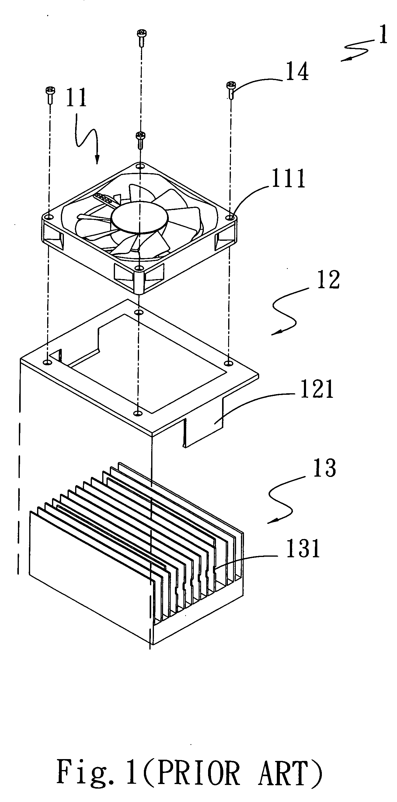
Cooling fan housing structrue
a technology of cooling fan and housing structure, which is applied in the direction of cooling/ventilation/heating modification, semiconductor device details, semiconductor/solid-state device details, etc., can solve the problems of increasing the manufacturing cost of the thermal module, bringing the whole thermal module b>1/b> to produce noise or vibration, and reducing labor and time costs. , the effect of quick and stable connection
- Summary
- Abstract
- Description
- Claims
- Application Information
AI Technical Summary
Benefits of technology
Problems solved by technology
Method used
Image

Examples
Embodiment Construction
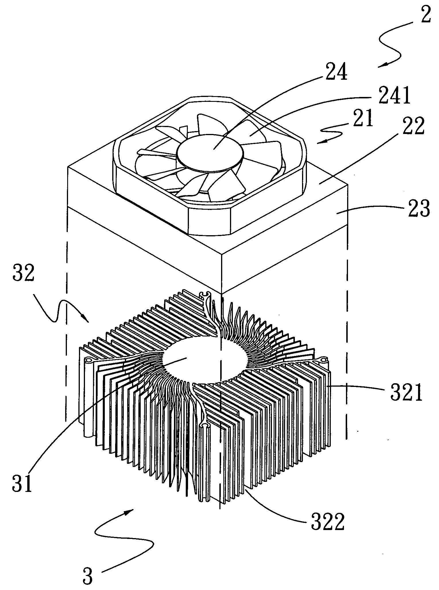
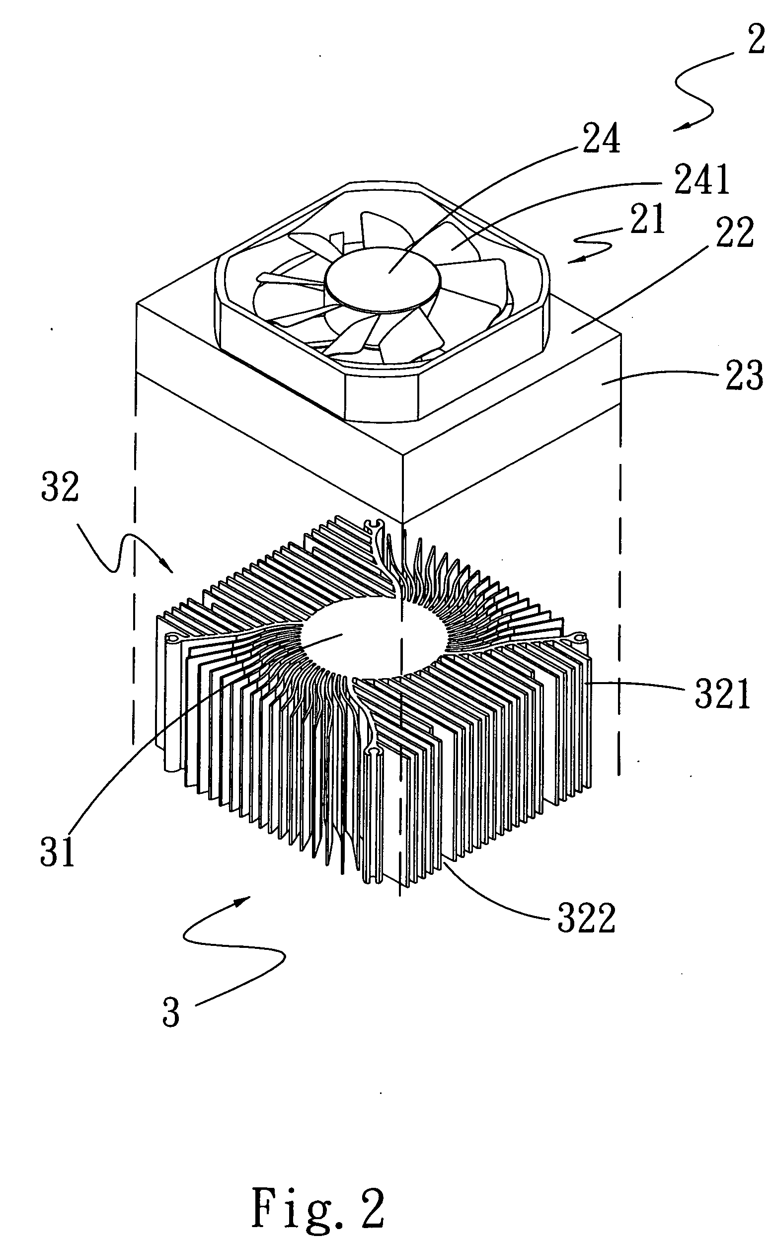
[0023]Please refer to FIGS. 2, 3, 4, 4A, 5, 5A, 6, 6A, 7 and 8. A cooling fan housing structure 2 according to a preferred embodiment of the present invention can be assembled to a heat sink 3. The cooling fan housing structure 2 includes a boosting portion 21, a top face 22, and an enclosing portion 23. The top face 22 is outward extended from an end of the boosting portion 21. The enclosing portion 23 is extended from an end of the top face 22 farther away from the boosting portion 21 in a vertical direction opposite to the boosting portion 21. The top face 22 and the enclosing portion 23 together cover one side of the heat sink 3. The top face 22 includes at least one projected element 221 for inserting into a heat-dissipating flow passage 322 formed between two adjacent radiating fins 321 of the heat sink 3, as can be seen from FIGS. 4 and 4A.
[0024]The projected element 221 further include an extended free end 2211, which can be tightly fitted and held in the heat-dissipating fl...
PUM
 Abstract
Description
Claims
Application Information