Electrical Interconnection System

Inactive Publication Date: 2010-06-03
RAYTHEON CO
View PDF22 Cites 7 Cited by
  • Summary
  • Abstract
  • Description
  • Claims
  • Application Information

AI Technical Summary

Benefits of technology

[0005]Some embodiments of the disclosure may provide numerous technical advantages. For example, one embodiment of the electrical interconnection system may provide denser packaging of electrical systems comprising multiple subsystems. Known implementations of connectors are relatively large in size and may be cumbersome to w

Problems solved by technology

Known implementations of connectors are relatively large in size and may be cumbers

Method used


Image

  • Electrical Interconnection System
  • Electrical Interconnection System
  • Electrical Interconnection System

Examples


Embodiment Construction

[0011]It should be understood at the outset that, although example implementations of embodiments are illustrated below, various embodiments may be implemented using any number of techniques, whether currently known or not. The present disclosure should in no way be limited to the example implementations, drawings, and techniques illustrated below. Additionally, the drawings are not necessarily drawn to scale.

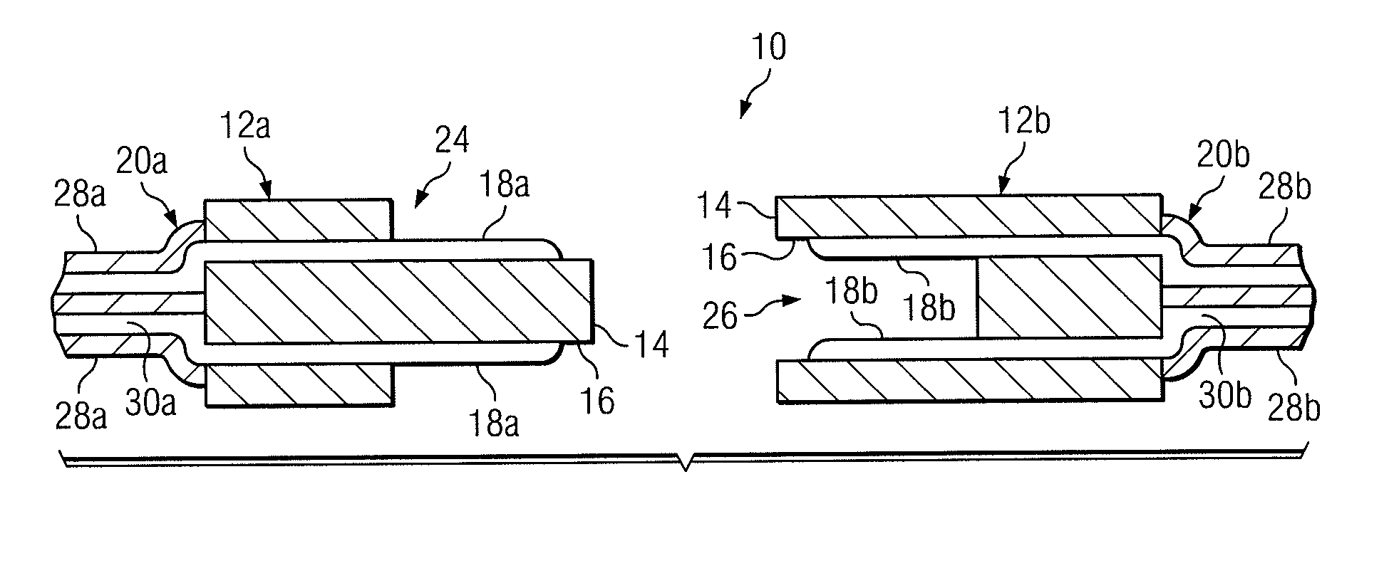
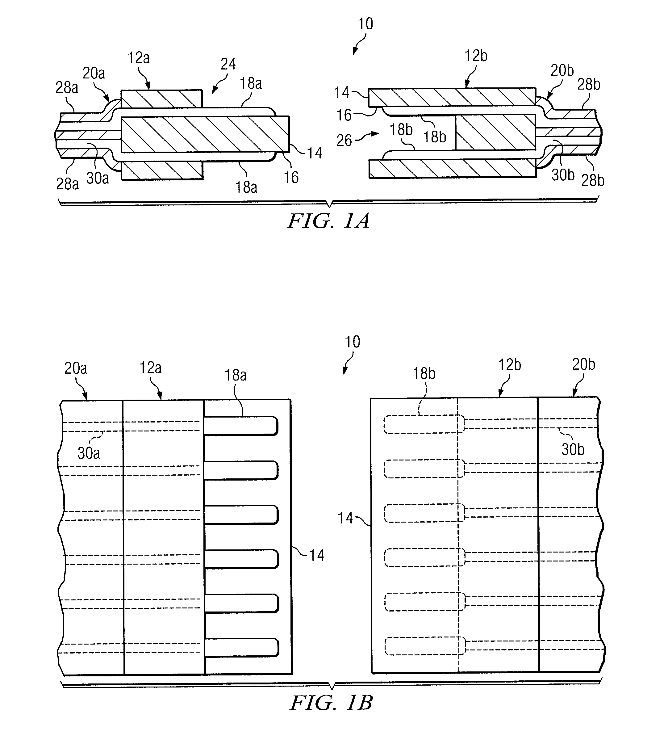
[0012]Complex electrical systems are often configured with multiple subsystems that function together to perform a useful function. These subsystems are usually coupled together using electrical interconnection systems that electrically couple certain nodes of one subsystem to those of another. Interconnection of electrical circuits to one another is usually provided by complementary connectors configured on multiple electrical circuits. Conventional connectors typically have a generally rigid structure, which may present various design problems when used in conjunction with el...


PUM


Abstract

According to one embodiment, an electrical interconnection system includes a pair of printed wiring boards formed of a printed wiring board material. Each printed wiring board has multiple surface pads formed on a surface of the printed wiring board adjacent its outer edge. The surface of each printed wiring board is operable to be placed adjacent to one another such that an electrical circuit coupled to one printed wiring board is electrically coupled to another electrical circuit of the other printed wiring board by contact of the surface pads of each printed wiring board with one another.

Description

RELATED APPLICATIONS[0001]This application claims priority to U.S. Provisional Patent Application Ser. No. 61 / 119,290, entitled “ELECTRICAL INTERCONNECTION SYSTEM,” which was filed on Dec. 2, 2008. U.S. Provisional Patent Application Ser. No. 61 / 119,290 is hereby incorporated by reference.TECHNICAL FIELD OF THE DISCLOSURE[0002]This disclosure generally relates to electrical devices, and more particularly, to an electrical interconnection system that may be used to couple electrical circuits to one another.BACKGROUND OF THE DISCLOSURE[0003]Complex electrical systems are often designed to have multiple subsystems that are electrically coupled together to perform some useful function. Each subsystem usually performs a portion of the overall functionality of its electrical system. The design of electrical systems with multiple subsystems may allow designers to accommodate these electrical systems in various types of enclosures. Multiple subsystems may also provide an efficient approach ...

Claims


Application Information

Patent Timeline
IPC IPC(8): H05K1/11
CPCH01R13/639H05K1/142H05K3/325H05K3/365H05K3/4015H01R24/60H05K2201/09845H05K2201/10409H01R12/721H01R2107/00H05K2201/09163H05K2201/09036H05K2201/09045H05K2201/0919
Inventor STRICKLAND, JULIE N.
Owner RAYTHEON CO
Why Eureka
Try Eureka