Method and Radio Base Station for Effective Spectrum Utilization

a radio base station and spectrum utilization technology, applied in the field of cell radio communication, can solve problems such as degrade system performan

Inactive Publication Date: 2010-06-03
TELEFON AB LM ERICSSON (PUBL)
View PDF5 Cites 87 Cited by
  • Summary
  • Abstract
  • Description
  • Claims
  • Application Information

AI Technical Summary

Benefits of technology

[0022]The main advantage of this invention is that it provides a solution to enable an LTE network to co-exist with another network in partially overlapping spectrum. This is made by using the third frequency band that can be used continuously over time for the L1 / l2control channels, whereas the second zone can be used for data traffic to the extent the second zone is available because of low exposure to interference. More specifically, this invention protects critical control signaling in the uplink and in the downlink in such a scenario.

Problems solved by technology

These spurious emissions are seen by the network into which they are emitted as interference, which may degrade system performance.
A problem with the traditional cellular deployment as described above is that it provides only a rigid framework in which operators can deploy their cellular networks.

Method used


Image

  • Method and Radio Base Station for Effective Spectrum Utilization
  • Method and Radio Base Station for Effective Spectrum Utilization
  • Method and Radio Base Station for Effective Spectrum Utilization

Examples


first embodiment

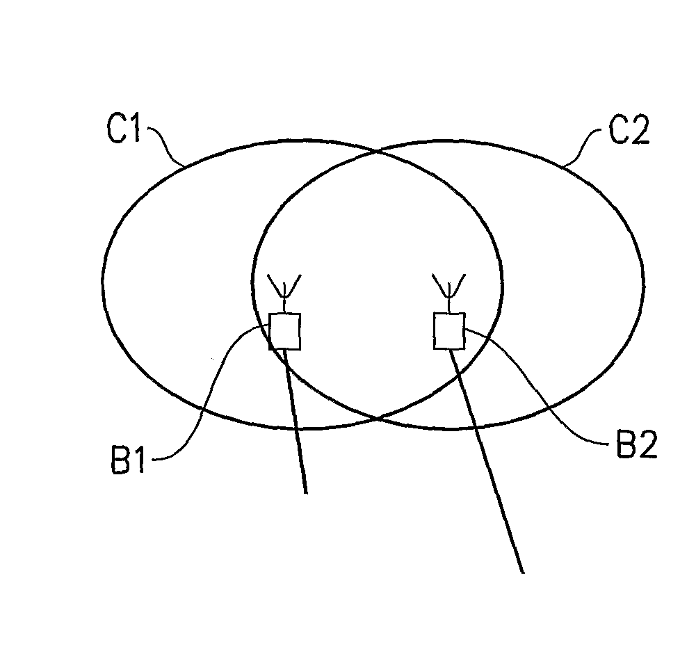
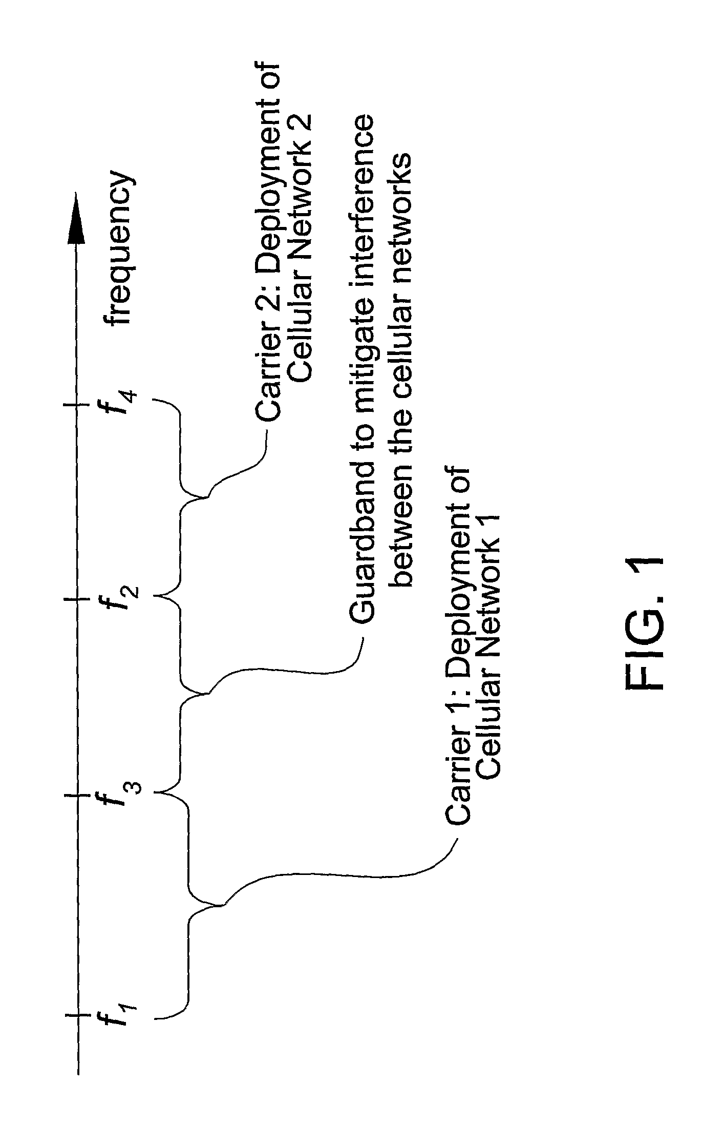
[0039]In a first embodiment two cellular radio networks covering geographical areas that overlap share a frequency zone in the spectrum. The invention will be described in the context of an LTE system partially sharing spectrum with a GSM. FIG. 4, is view over the first cell C1, belonging to the LTE system and served by an LTE RBS (Radio Base Station), B1. The cell C1 is using an LTE carrier defined to be 5 MHz. There is also a second cell C2, served by a second RBS, B2, that belongs to the GSM network and whose geographical coverage, in the example, partly overlaps with the first cell C1. FIG. 6 discloses a frequency axis, wherein the spectrum is divided into 3 separate frequency zones FZ1, FZ2, FZ3:[0040]Frequency Zone 1, FZ1 can only be used by the GSM carriers allocated at those frequencies. They are outside the 5 MHz carrier of LTE.[0041]Frequency Zone 2, FZ2 can be used by both the LTE carrier and the GSM carriers at those frequencies. In order to avoid collisions, the usage o...

second embodiment

[0077]In a second embodiment, the LTE base station B1 receives information from the GSM system, on what parts of the second zone, FZ2, that is occupied by GSM. FIG. 13, is almost the same as FIG. 5, with the addition of a BSC, in the GSM system with a link 21, the LTE base station. The GSM BSC reserves parts of frequency zone 2, for the GSM and informs of this to the LTE base station B1. The Control Channel manager of the LTE base station, B1, is informed of this and only frequencies in zone 2, outside what is reserved by the GSM are scheduled.

[0078]Hierarchical Cell Structure

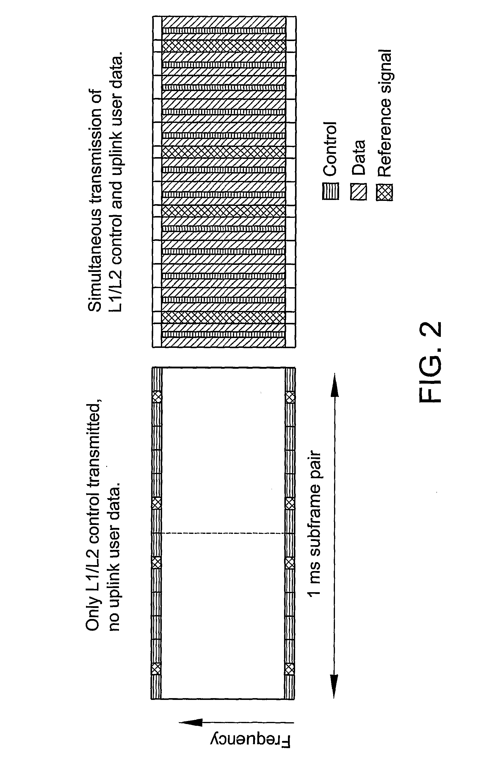
[0079]The L1 / L2 control channel structure as disclosed in FIGS. 7 and 8, is advantageous to use also in a hierarchical cell structure when cell in different layers of the hierarchical structure shares the same frequency band for long period. FIG. 9 discloses such a hierarchical cell structure with a outdoor macro-RBS, 41 covering an wide outdoor cell. Within the cell an apartment building has a small home base ...


PUM


Abstract

The present invention relates to radio communication in a cellular network and in particular to the sharing of a frequency spectrum with another network. The object is to enable robust communication in the shared band. The solution is to allocate a third band for communication in a cell. A L1/L2 control channel may be transmitted in the third band only, whereas data can be transmitted in the shared band. The L1/L2 control channel support the data communication in the shared band. The invention relates to a method and a radio base station.

Description

TECHNICAL FIELD OF THE INVENTION[0001]The present invention relates to cellular radio communication and in particular to two methods for efficient frequency spectrum utilization. It also relates to a radio base station adapted for performing one of the methods.DESCRIPTION OF RELATED ART[0002]In traditional planning of cellular networks, a range of contiguous radio frequencies (referred to as a carrier) are allocated to a single radio network. This is depicted with a frequency axis in FIG. 1, where Carrier 1, from frequency f1 to f2, is allocated to Cellular Network 1 and Carrier 2, from frequency f3 to f4, is allocated to Cellular Network 2. Between the two carriers, a Guard-Band is typically included in order to reduce the spurious emissions emitted between the cellular networks. These spurious emissions are seen by the network into which they are emitted as interference, which may degrade system performance.[0003]It is customary in cellular network design to spread critical inform...

Claims


Application Information

Patent Timeline
Patent Type & Authority Applications(United States)
IPC IPC(8): H04W72/04H04W48/12
CPCH04W16/14H04W48/12H04W16/16
Inventor WESTERBERG, ERIKOLSSON, ANDREASPARKVALL, STEFANTYNDERFELDT, TOBIASEKSTROM, HANNES
Owner TELEFON AB LM ERICSSON (PUBL)
Why Eureka
Try Eureka