Antenna assembly for service station

a technology for service stations and antennas, applied in the directions of polarisation/directional diversity, packaging under special atmospheric conditions, wireless commuication services, etc., can solve the problems of prohibitively expensive replacement of the system, difficult installation, maintenance and upgrading of the automated fuel payment system, and service stations using obsolete automated fuel payment systems

Inactive Publication Date: 2013-01-29
GASNGO R&D LTD
View PDF71 Cites 5 Cited by
  • Summary
  • Abstract
  • Description
  • Claims
  • Application Information

AI Technical Summary

Benefits of technology

[0027]The present invention is of antenna assemblies, of service stations provided with such antenna assemblies and methods for establishing wireless communication in a service station between a service station controller and wireless transmitters having limited power supplies (that is to say, generally having self-contained power supplies) such as fuel dispensing nozzle mounted vehicle identification tag readers or vehicle mounted transmitters such as second vehicle identification tags described in the PCT patent applications published as WO 2007 / 049273 and WO 2007 / 049274. Embodiments of the present invention successfully address at least some of the disadvantages of the prior art, by providing robust communication between a service station controller and wireless transmitters having limited power supplies.
[0057]In embodiments, the transmission antenna of entities that are vehicle-mounted transmitters are mounted in the vehicle so that the transmission antenna will substantially always have a significant component parallel to at least one of the reception antennae of the antenna assembly. For example, in embodiments, the transmission antennae of entities that are vehicle-mounted transmitters are oriented substantially in parallel with the ground (X-Z plane) so as to have little or no component perpendicular to the ground (Y-axis) and the orientations of two reception antennae of the antenna assembly define a plane that is substantially parallel with the ground (X-Z plane). Such an orientation has an additional advantage that there is less interference with other sources of radiofrequency energy. For example, in embodiments, the transmission antennae of entities that are vehicle-mounted transmitters are oriented having a significant component substantially parallel with the Y-axis and the orientations of two reception antennae of the antenna assembly define a plane that is substantially perpendicular with the ground (X-Y or Y-Z planes).
[0059]In embodiments, the antenna assembly is mounted on a structure so that the plane defined by the orientation of the first and second antennae is substantially parallel to the ground (X-Z plane), the back side of the plane defined by the orientation of the first and second antennae substantially faces upwards (skywards) and the front side of the plane substantially faces the ground. In some such embodiments, the antenna assembly is mounted so that the plane defined by the antenna is at least about 3 meters, at least about 4 meters and even at least about 5 meters above the ground, providing unobstructed line-of-sight to most transmission antenna of the entities without interference of trucks and other tall vehicles. In some such embodiments, such mounting allows a reduction of radiofrequency noise and interference received by the antenna assembly from the environment without compromising coverage of substantially the entire service station.
[0066]In embodiments of the method of the present invention, the antenna assembly is mounted on a structure so that the plane defined by the orientation of the first and second antennae is substantially parallel to the ground (X-Z plane), the back side of the plane defined by the orientation of the first and second antennae substantially faces upwards (skywards) and the front side of the plane substantially faces the ground. In some such embodiments, the antenna assembly is mounted so that the plane defined by the antenna is at least about 3 meters, at least about 4 meters and even at least about 5 meters above the ground. In some such embodiments, such mounting allows a reduction of noise and interference received by the antenna assembly without compromising coverage of substantially the entire service station.

Problems solved by technology

In a large part due to the use of wired communication between the various subsystems especially between the identification tag reading antenna and the tag reading transceiver, and between the tag reader station communication transmitter and the service station controller, installation, maintenance and upgrading of an automated fuel payment system is difficult.
Once a fuel station has invested in a given system, it is often prohibitively expensive to replace the system, causing service stations to use obsolete automated fuel payment systems.
A problem with the teachings of the above-referenced PCT patent applications is that the wireless communication systems described to date are not sufficiently robust, so that under certain conditions a service station controller fails to establish or maintain wireless communication with a transmitter of a nozzle-mounted vehicle identification tag reader or of a vehicle-mounted active identification tag.
The Inventor has identified that one of the challenges encountered when implementing wireless communication between a service station controller and a nozzle-mounted vehicle identification tag reader or a vehicle-mounted active identification tag is related to antenna polarization.
Such frequencies are very susceptible to coupling loss resulting from mismatch between the polarization of a transmission antenna and a reception antenna, e.g., between the transmission antenna of a nozzle-mounted vehicle identification tag reader or of a vehicle-mounted active identification tag and the reception antenna of the receiver of the service station controller.
In an automated fuel payment system it is not practical to ensure sufficiently similar orientation of the reception antenna of a receiver of a service station controller and the transmission antenna of a nozzle-mounted transmission antenna of a vehicle identification tag reader transmitter.
In an automated fuel payment system it is not practical to ensure sufficiently similar orientation of the reception antenna of a receiver of a service station controller and the transmission antenna of a vehicle-mounted active identification tag.
It is impractical to provide a small, portable and cheap transmitter such as a vehicle identification tag reader transmitter with excess transmission power.
First, as the tag reader transmitter is mounted on a fuel dispensing nozzle, the transmitter is in close proximity to explosive gasoline fumes.
The higher the power of such a transmitter the more likely it is that the transmitter produces sparks or generates excess heat, potentially leading to a catastrophic situation.
It is also clear that it is impractical to provide a self-contained vehicle-mounted active identification tag including an autonomous power source with excess transmission power.
Automatically adjustable antenna are complex, expensive, difficult to implement and susceptible to malfunction.
Further, as the reception antenna associated with the receiver of a service station controller must typically communicate with a plurality of differently oriented nozzle-mounted vehicle identification tag readers and a plurality of differently oriented vehicle-mounted active identification tags, it is impractical to use an adjustable reception antenna.
Circularly polarized antennae are generally more expensive, complex and bulky than other antenna types.
Low gain VHF and UHF transmission antennae are inefficient, wasteful of power, have a relatively short range and have relatively high noise.
This is not an ideal solution due to the added expense of manufacture, installation and maintenance of wireless relays.

Method used


Image

  • Antenna assembly for service station
  • Antenna assembly for service station
  • Antenna assembly for service station

Examples


first embodiment

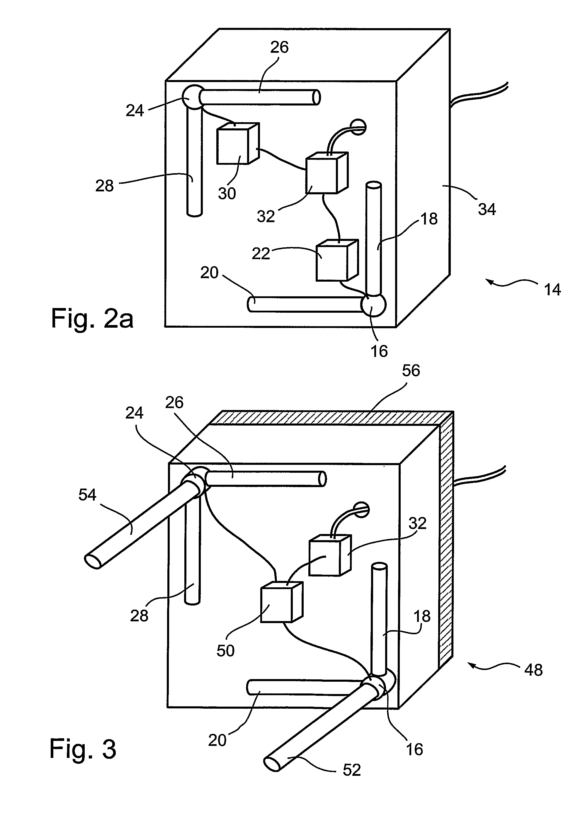
[0114]an antenna assembly of the present invention, antenna assembly 14 is schematically depicted in FIG. 2A.

[0115]Antenna assembly 14 includes a reception antenna holder 16 to which are attached a vertically oriented first reception antenna 18 and a horizontally oriented second reception antenna 20. Reception antenna holder 16 holds first reception antenna 18 at a 90° angle from second reception antenna 20, so that antennae 18 and 20 define a plane. As both first antenna 18 and second antenna 20 are simple linearly polarized omnidirectional rod antenna, the orientations of the antennae define a plane that is substantially coplanar with the plane defined by the physical antennae. Functionally associated with first antenna 18 is a radio frequency receiver 22 so that receiver 22 is able to receive radio frequency signals through first antenna 18. Independently of the association with first antenna 18, receiver 22 is also functionally associated with second antenna 20 so that receiver ...

second embodiment

[0126]In FIG. 3 is depicted an antenna assembly of the present invention, antenna assembly 48.

[0127]Antenna assembly 48 of the present invention is substantially similar to antenna assembly 14. Unlike antenna assembly 14 that comprises receiver 22 separate from transmitter 30, antenna assembly 48 comprises a transceiver 50 where the receiver function of transceiver 50 is functionally associated with a first antenna 18 and a second antenna 20 and the transmitter function of transceiver 50 is functionally associated with a third antenna 28 and a fourth antenna 26.

[0128]A significant difference between antenna assembly 48 and antenna assembly 14 is that antenna assembly 48 comprises a fifth reception antenna 52 functionally associated with the receiver function of transceiver 50 independently of first antenna 18 and second antenna 20. Fifth antenna 52 is oriented at 90° relative to both first antenna 18 and second antenna 20 so therefore protrudes from and is necessarily substantially ...

third embodiment

[0132]In FIG. 4 is depicted an antenna assembly of the present invention, antenna assembly 58.

[0133]Antenna assembly 58 of the present invention is substantially similar to antenna assembly 14. Unlike antenna assembly 14 that comprises a receiver 22 and a transmitter 30, antenna assembly 58 does not comprise a receiver or a transmitter, but rather only includes a controller / adaptor 32 which is configured to interface with other devices, to receive power, to receive signals which are to be transmitted from other devices and to forward signals which are received by to other devices, for example signals to and from a transceiver of a service station controller.

[0134]A significant difference between antenna assembly 58 and antenna assembly 14 is that antenna assembly does not comprise dedicated transmission antennae such as third antenna 28 and fourth antenna 26 of antenna assembly 14. Rather antenna assembly 58 comprises a first antenna 18 (a vertically-oriented linearly polarized omni...


PUM


Abstract

Disclosed are antenna assemblies suitable for establishing wireless communication with entities that have variable or indeterminate antenna orientation, especially entities having a limited power supply, the antenna assemblies comprising two linearly polarized reception antennae (18, 20) positioned so that the orientation of the antennae define a plane. Disclosed are also service station provided with such an antenna assembly. Disclosed are also methods of establishing wireless communication in a service station between a service station controller and entities that have variable or indeterminate antenna orientation, especially entities having a limited power supply.

Description

RELATED APPLICATIONS[0001]This application is a National Phase of PCT Patent Application No. PCT / IL2008 / 000349 having International filing date of Mar. 13, 2008, which claims the benefit of U.S. Provisional Patent Application No. 60 / 906,515 filed on Mar. 13, 2007. The contents of the above applications are all incorporated herein by reference.FIELD AND BACKGROUND OF THE INVENTION[0002]The present invention relates to the fields of purchase authorization and radio frequency communication and, more particularly, to antenna assemblies, methods and service stations useful, for example, for fuel-purchase authorization.[0003]In the past a gas station was primarily a location to purchase fuel for a vehicle and occasionally to purchase comestibles and products associated with vehicular operation. Increasingly, gas stations are transforming into service stations, becoming one of the most important retail venues in industrialized society. The reasons for the increasing importance of service s...

Claims


Application Information

Patent Timeline
Patent Type & Authority Patents(United States)
IPC IPC(8): H04B1/38B67D7/34
CPCH01Q1/2216H01Q21/28H04B7/10H01Q1/2208
Inventor WEITZHANDLER, SHIMONVILNAI, YOAVYALON, AVI
Owner GASNGO R&D LTD
Why Eureka
Try Eureka