Implantable lead

Active Publication Date: 2010-06-03
WL GORE & ASSOC INC
View PDF73 Cites 71 Cited by
  • Summary
  • Abstract
  • Description
  • Claims
  • Application Information

AI Technical Summary

Benefits of technology

[0008]An implantable lead is described that offers good flexibility, fatigue resistance and flex life, improved reliability, high abrasion, fatigue, and corrosion resistance, high tensile strength and effective electrode tissue contact with a small, isodiametric profile and low risk of tissue damage during extraction. The lead also offers similar defibrillation impedances and thresholds, pacing impedances and thresholds, and sensing R-wave amplitudes when compared to commercially available leads. In one embodiment the lead is provided with both defibrillation electrodes and pacing/sensing electrodes. For defibrillation/pacing leads, the lead diameter may be as small as six French, five French or even sm

Problems solved by technology

Medical leads with discrete connectors may suffer from decreased reliability due to connector interfaces serving as points of failure.
This may lead to increased tissue attachment in these regions and commensurate difficulty in lead extraction (sometimes necessary in cases of i

Method used


Image

  • Implantable lead
  • Implantable lead
  • Implantable lead

Examples


Example

DETAILED DESCRIPTION OF THE DRAWINGS

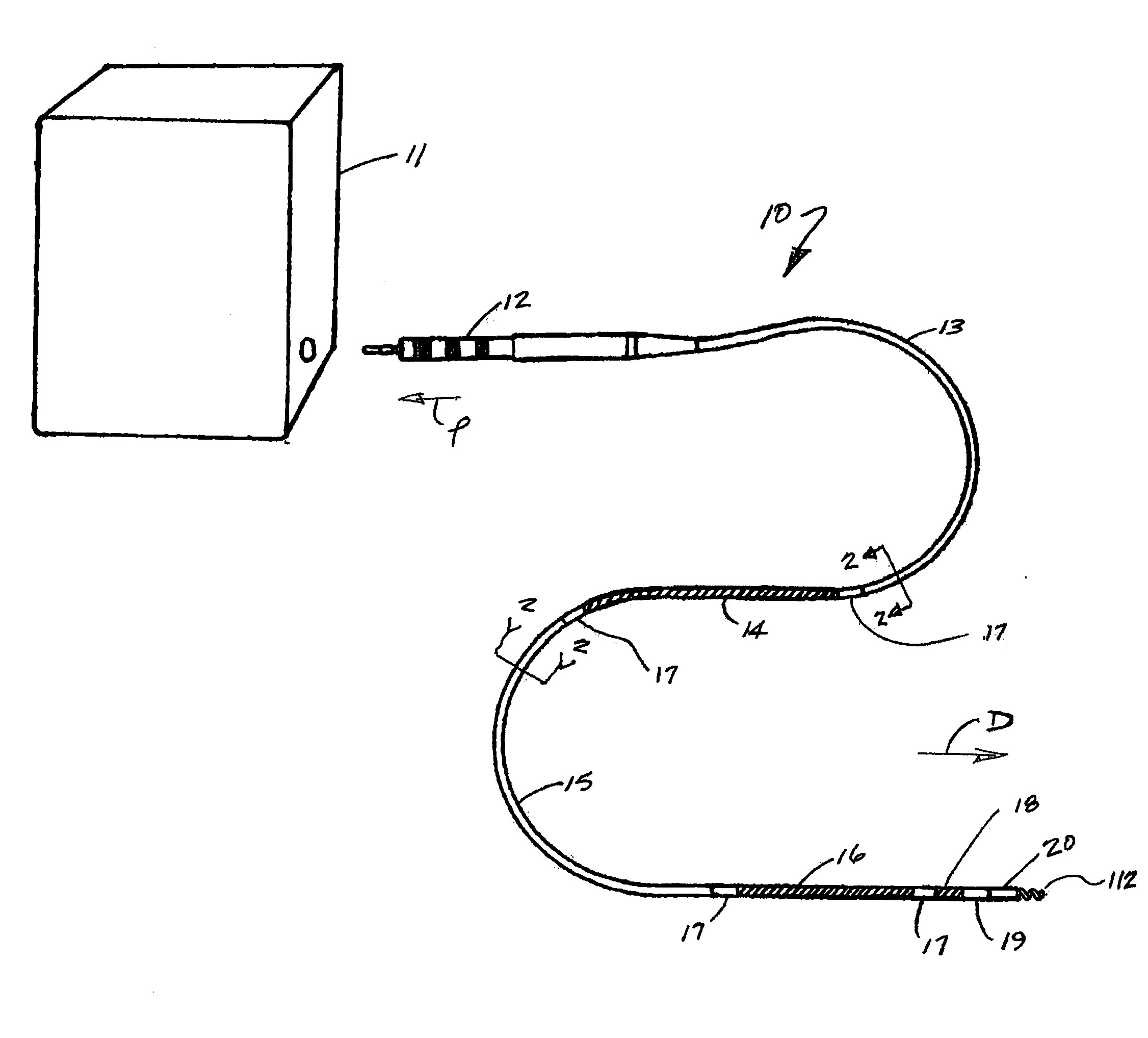
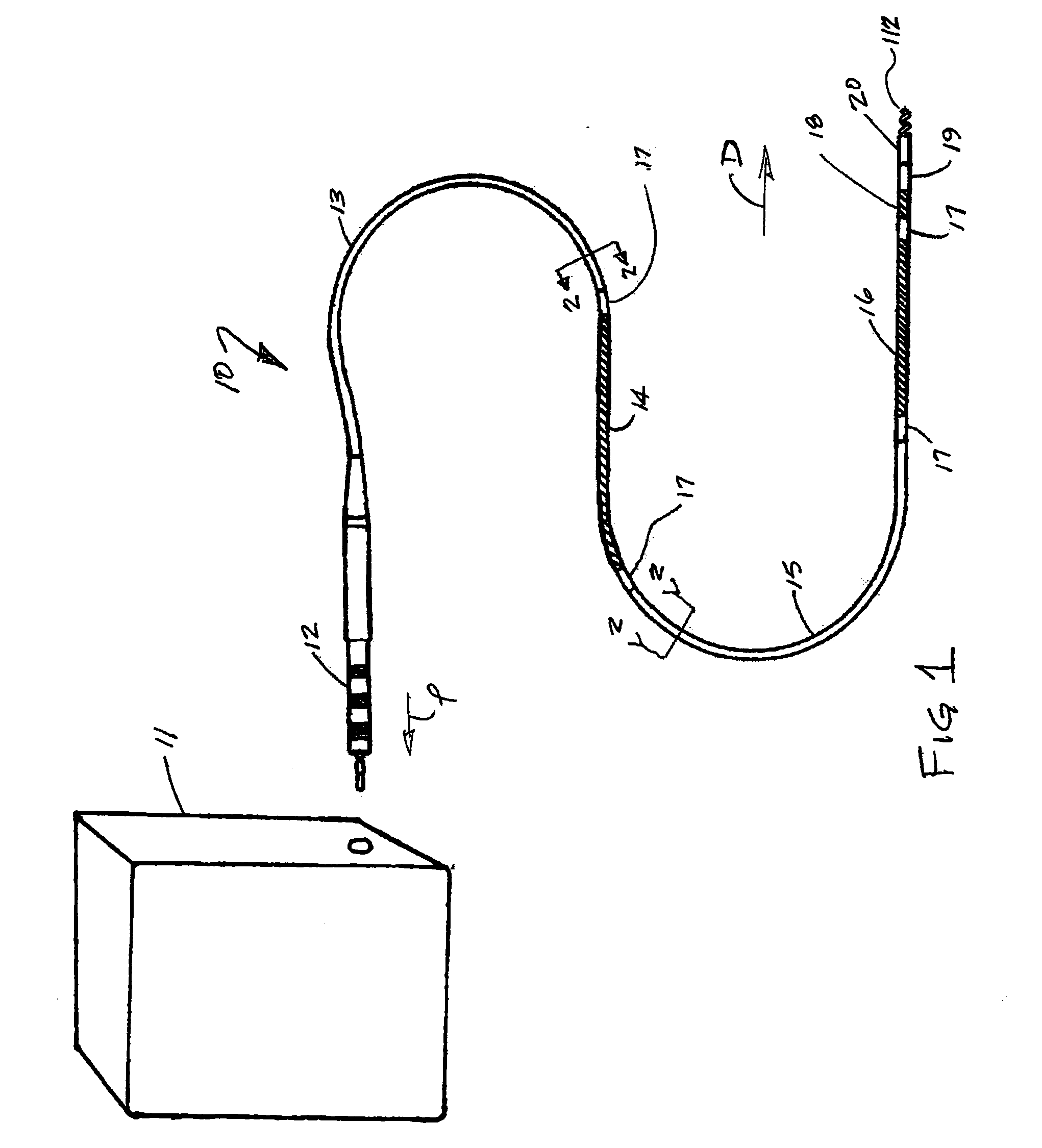
[0075]FIG. 1 is a perspective view of a typical implantable lead assembly 10 as described herein, showing a proximally-located electrical connector 12 to enable lead 10 to be connected to a suitable power source or sensing and control system 11, the proximal defibrillator electrode 14, the distal defibrillator electrode 16, the sensing electrode 18 and the distal tip electrode assembly 20 attached at the distal end of lead 10 by tip connection region 19. Lead 10 also includes intervening insulated length portions 13 and 15, as well as seal components 17 located at each end of both defibrillator electrodes 14 and 16. It is apparent that any or all of the length portions shown can be made to any desired length.

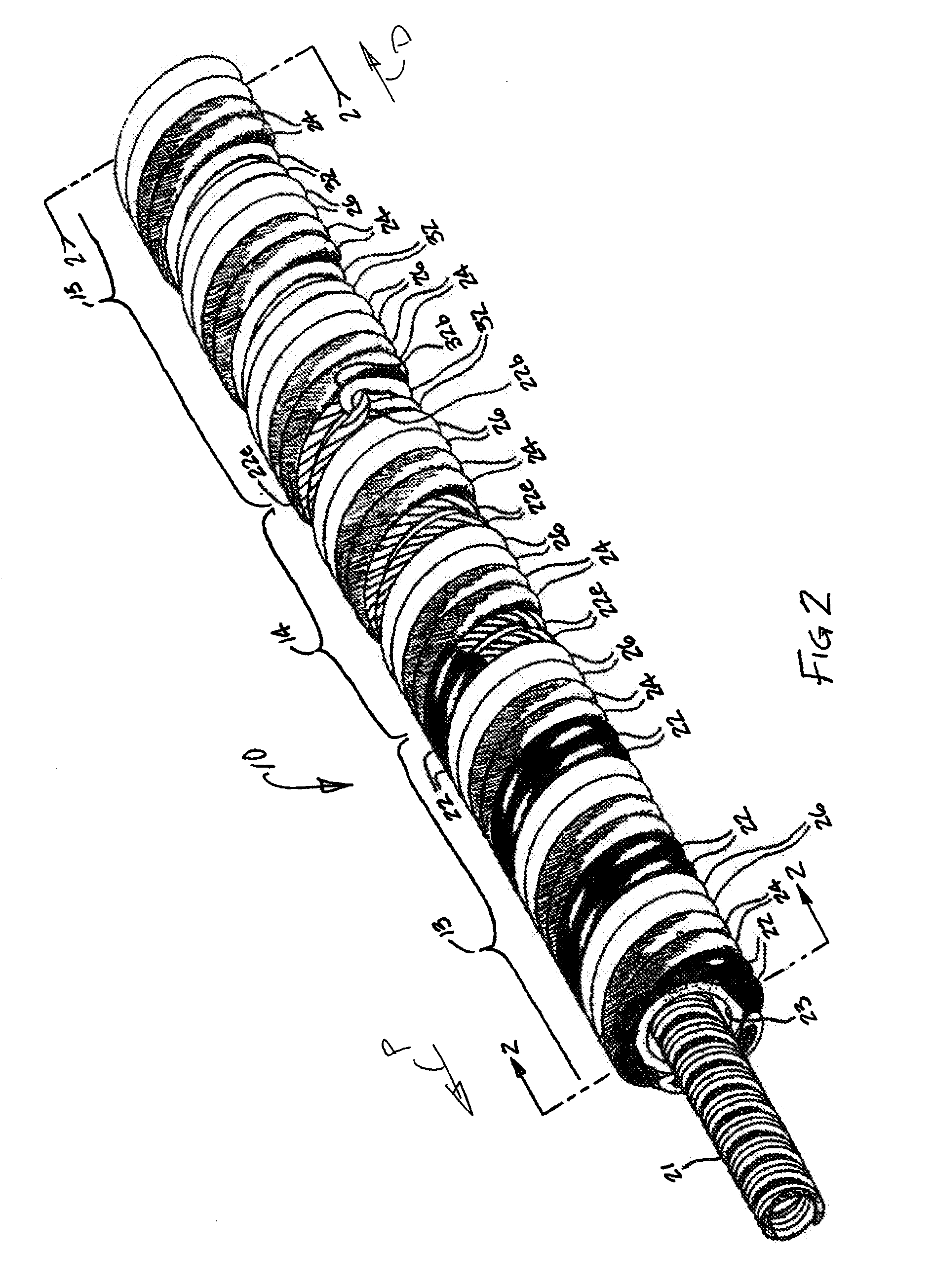
[0076]FIG. 2 is a perspective view of a portion of the length of a lead 10 such as shown in FIG. 1, excluding outer coverings. The portion shown in FIG. 2 is indicated by the break lines “2” shown in FIG. 1 and includes the proximal defibrilla...


PUM

PropertyMeasurementUnit
Diameteraaaaaaaaaa
Lengthaaaaaaaaaa
Electrical conductivityaaaaaaaaaa

Abstract

A highly flexible implantable lead that offers improved flexibility, fatigue life and fatigue and abrasion resistance improved reliability, effective electrode tissue contact with a small diameter and low risk of tissue damage during extraction. In one embodiment the lead is provided with both defibrillation electrodes and pacing/sensing electrodes. For defibrillation/pacing leads, the lead diameter may be as small as six French or smaller. The construction utilizes helically wound conductors. For leads incorporating multiple separate conductors, many of the helically wound conductors are arranged in a multi-filar relationship. Preferably, each conductor is a length of wire that is uninsulated at about the middle of its length to create an electrode, wherein the conductor is folded in half at about the middle of the length to create first and second length segments that constitute parallel conductors.

Description

CROSS REFERENCE TO RELATED APPLICATIONS[0001]This application claims priority to U.S. Patent Application Ser. No. 61 / 112,600 filed Nov. 7, 2008.FIELD OF THE INVENTION[0002]The present invention relates to the field of implantable electrophysiology leads including cardiac defibrillation and pacing leads, diagnostic leads and neurological stimulation leads.BACKGROUND OF THE INVENTION[0003]Implantable medical leads are used in a variety of applications to conduct energy (e.g., electrical, photonic, etc.) between energy sources and various portions of the body. Diagnostic leads are implanted to measure physiological parameters over time, for example blood pressure, or collect and transmit physiological data such as nerve impulses and cardiac rhythm data. Stimulation leads discretely deliver energy to targeted tissues. Neurological stimulation leads are used to block pain, for example. Cardiac stimulation leads are used to deliver low or high voltage electrical energy to pace or defibril...

Claims


Application Information

Patent Timeline
IPC IPC(8): A61N1/05H01R43/16H01R24/04A61B5/296H01R24/58
CPCA61N1/05Y10T29/49204A61N1/0563
Inventor DUNCAN, JEFFREY B.HOPKINSON, AARON J.MCDANIEL, THOMAS R.VONESH, MICHAEL J.WIERSDORF, JASON M.
Owner WL GORE & ASSOC INC
Why Eureka
Try Eureka