Method for forming a multiple material golf club head

Inactive Publication Date: 2010-06-10
CALLAWAY GOLF CO
View PDF101 Cites 14 Cited by
  • Summary
  • Abstract
  • Description
  • Claims
  • Application Information

AI Technical Summary

Benefits of technology

[0019]This present invention is unique from other composite crown golf club heads or high performance multi-piece construction golf club heads because material is not wasted beyond what is necessary to form the golf club head. In traditional composite crown golf club heads, the whole golf club head is formed (either by casting or welding) and then an opening is cut from this whole golf club head for the composite crown. In the high performance multi-piece c

Problems solved by technology

More specifically, the finishing process for we

Method used


Image

  • Method for forming a multiple material golf club head
  • Method for forming a multiple material golf club head
  • Method for forming a multiple material golf club head

Examples


Example

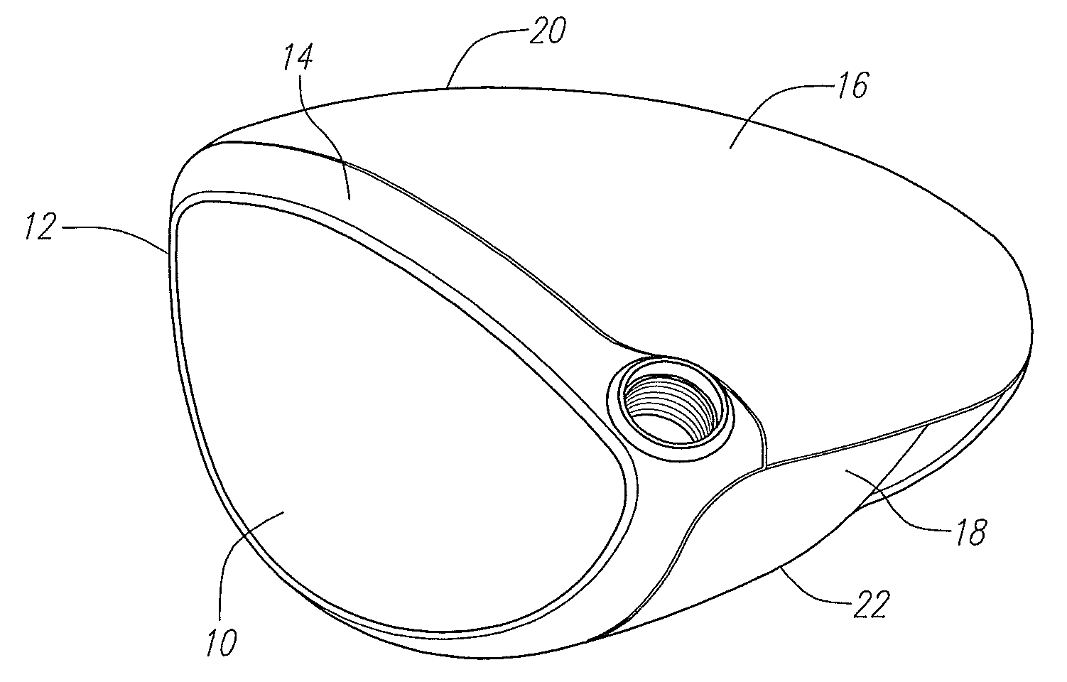
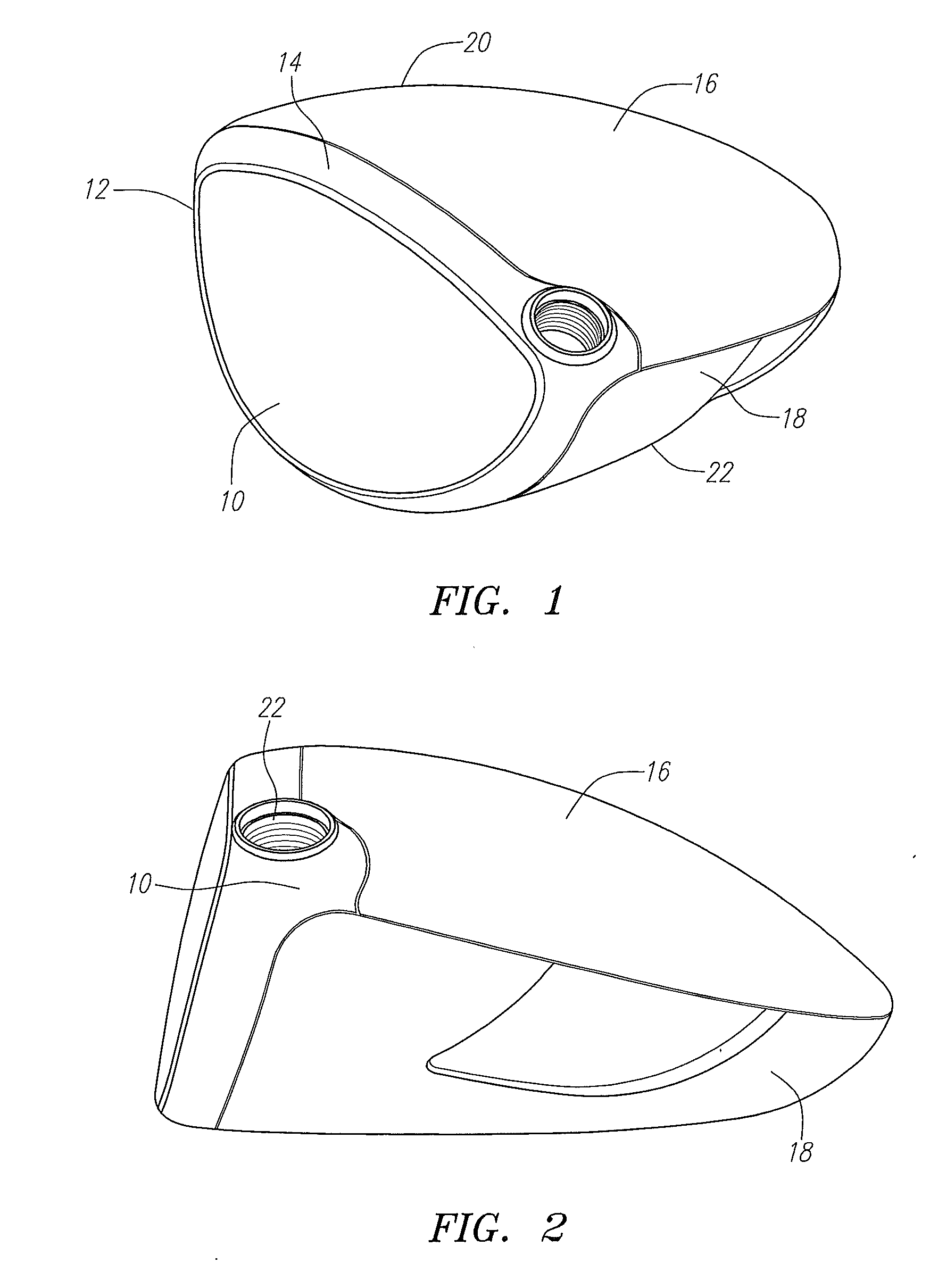
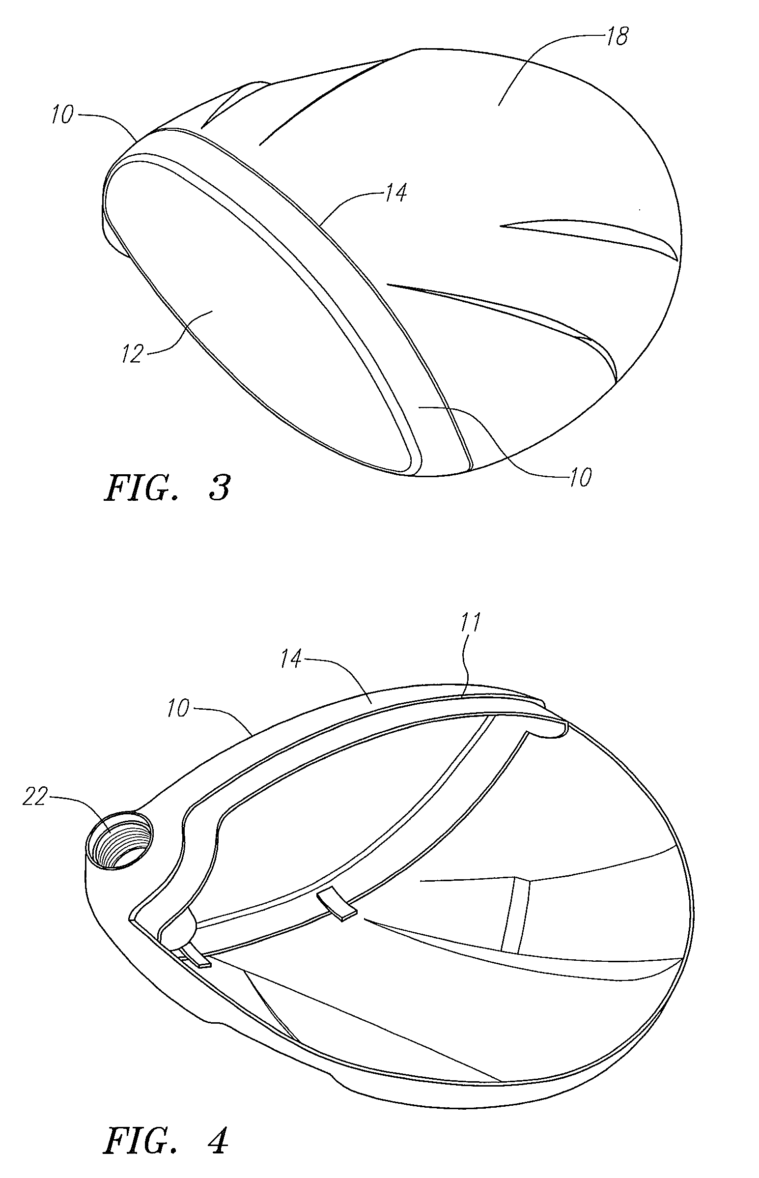
[0030]The process of the present invention preferably includes the manufacture of a cast face component 10 and a stamped metal sole component 18. The face component 10 and the sole component 18 are assembled together in a welding fixture. The welding fixture locates on the inside of the face component 10 and inside of the sole component 18. The welding fixture also locates on some sections of the outside surfaces of the face component 10 and the sole component 18. The crown component 16 is preferably formed from a carbon composite. Once the face component 10 and sole component 18 are welded into a golf club head subassembly, the golf club head subassembly is polished and prepared for adhesive bonding. The composite crown made by compression mold is bonded to the golf club head subassembly using an adhesive. After the adhesive cures, the unfinished golf club head is cleaned and finished (typically painting).

[0031]As shown in FIGS. 1-8, a golf club head 20 comprises a face component 1...


PUM

PropertyMeasurementUnit
Lengthaaaaaaaaaa
Lengthaaaaaaaaaa
Massaaaaaaaaaa

Abstract

A method for forming a golf club head having a composite crown is disclosed herein. The method includes casting a face component, stamping a sole component, compression molding a crown component, welding the face component to the sole component to create a subassembly, and bonding the crown component to the subassembly.

Description

CROSS REFERENCES TO RELATED APPLICATIONS[0001]The present application claims priority to U.S. Provisional Patent Application No. 61 / 119,804, filed on Dec. 4, 2008.STATEMENT REGARDING FEDERALLY SPONSORED RESEARCH OR DEVELOPMENT[0002]Not ApplicableBACKGROUND OF THE INVENTION[0003]1. Field of the Invention[0004]The present invention relates to a method for forming a multiple material golf club head.[0005]2. Description of the Related Art[0006]The prior art discloses several methods for forming a golf club head.[0007]One method is full casting which involves casting the entire golf club head, usually with a face pull tool. Duquette et al., U.S. Pat. No. 6,978,976 for a Magnetized Core With Pneumatic Release System For Creating A Wax Mold For A Golf Club Head describes certain aspects of the full casting method. Then a face insert is welded to then golf club head.[0008]Another method is using a full casting method, using a face pull tool and then cutting a crown opening. A graphite crown...

Claims


Application Information

Patent Timeline
IPC IPC(8): B23P17/00
CPCA63B53/0466A63B2053/0408A63B2053/0412A63B2053/0416Y10T29/49988A63B2209/023A63B2209/00A63B2053/0433A63B2053/0437A63B2053/0458A63B60/00A63B53/0412A63B53/0408A63B53/0416A63B53/0437A63B53/0433A63B53/0458
Inventor DAWSON, PATRICKRICE, BRADLEY C.
Owner CALLAWAY GOLF CO
Why Eureka
Try Eureka