Power conversion apparatus and junction box

a technology of power conversion apparatus and junction box, which is applied in the direction of dc-ac conversion without reversal, transportation and packaging, and propulsion by batteries/cells, etc. it can solve the problems of increasing the number of manufacturing steps, and forming the lid partially to form the interlock mechanism, etc., and achieves the effect of not adding additional costs

Active Publication Date: 2016-09-22
PANASONIC INTELLECTUAL PROPERTY MANAGEMENT CO LTD
View PDF8 Cites 9 Cited by
  • Summary
  • Abstract
  • Description
  • Claims
  • Application Information

AI Technical Summary

Benefits of technology

[0009]According to the present invention, it is made possible to ensure sa

Problems solved by technology

However, when the work window is formed in a range that is long in a certain direction, there arises a problem of how a lid partially forming the interlock mechanism should be formed.
However, providing the lid with a mechanism (e.g., protrusion) to turn an interlock switch makes molding difficult compared with the case where the lid is made of resin, and causes an increase in the number of manufacturing steps, thus causi

Method used


Image

  • Power conversion apparatus and junction box
  • Power conversion apparatus and junction box
  • Power conversion apparatus and junction box

Examples


embodiment 1

[0022]Hereinafter, a description will be given of a power conversion apparatus according to Embodiment 1 of the present invention with reference to the accompanying drawings.

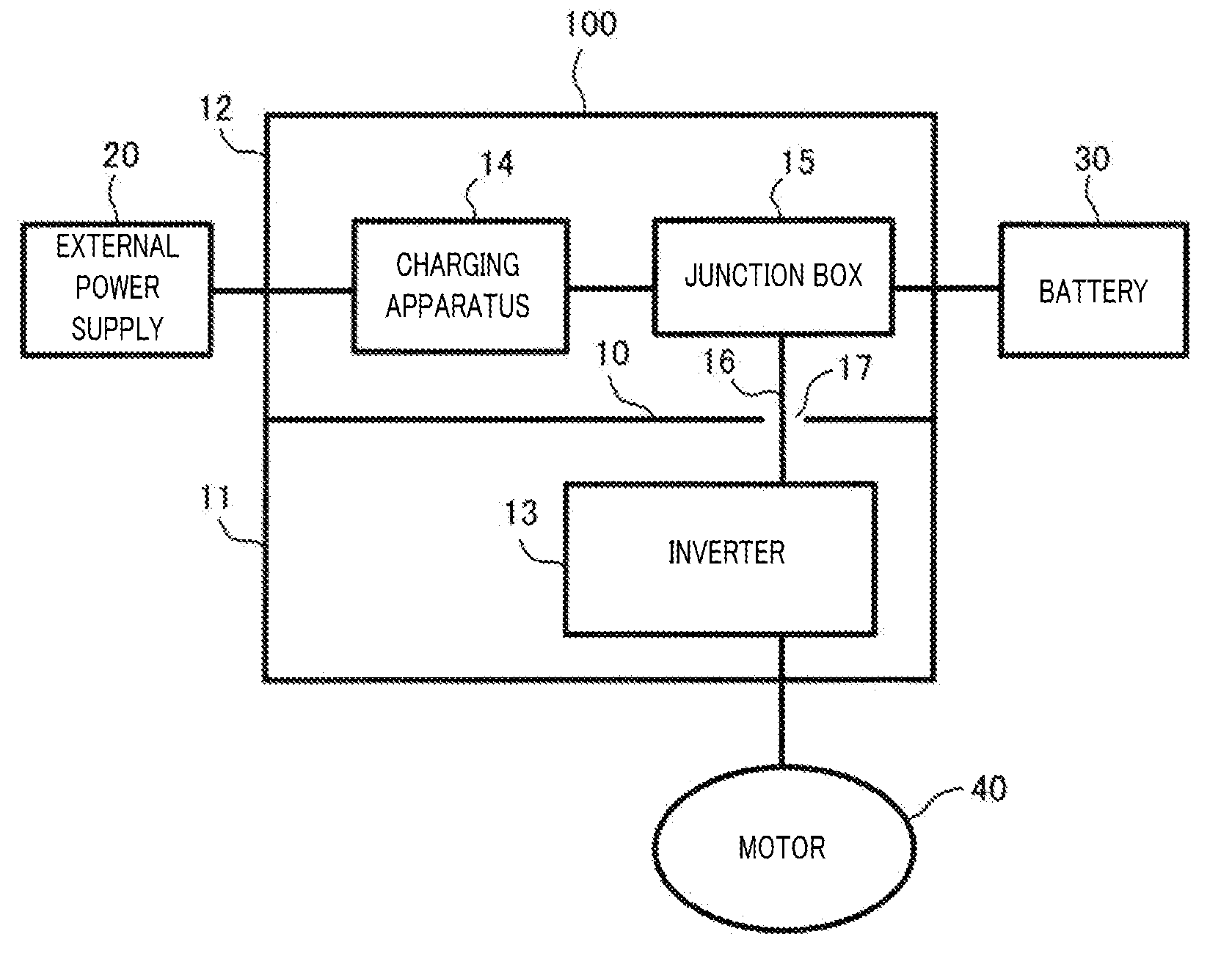
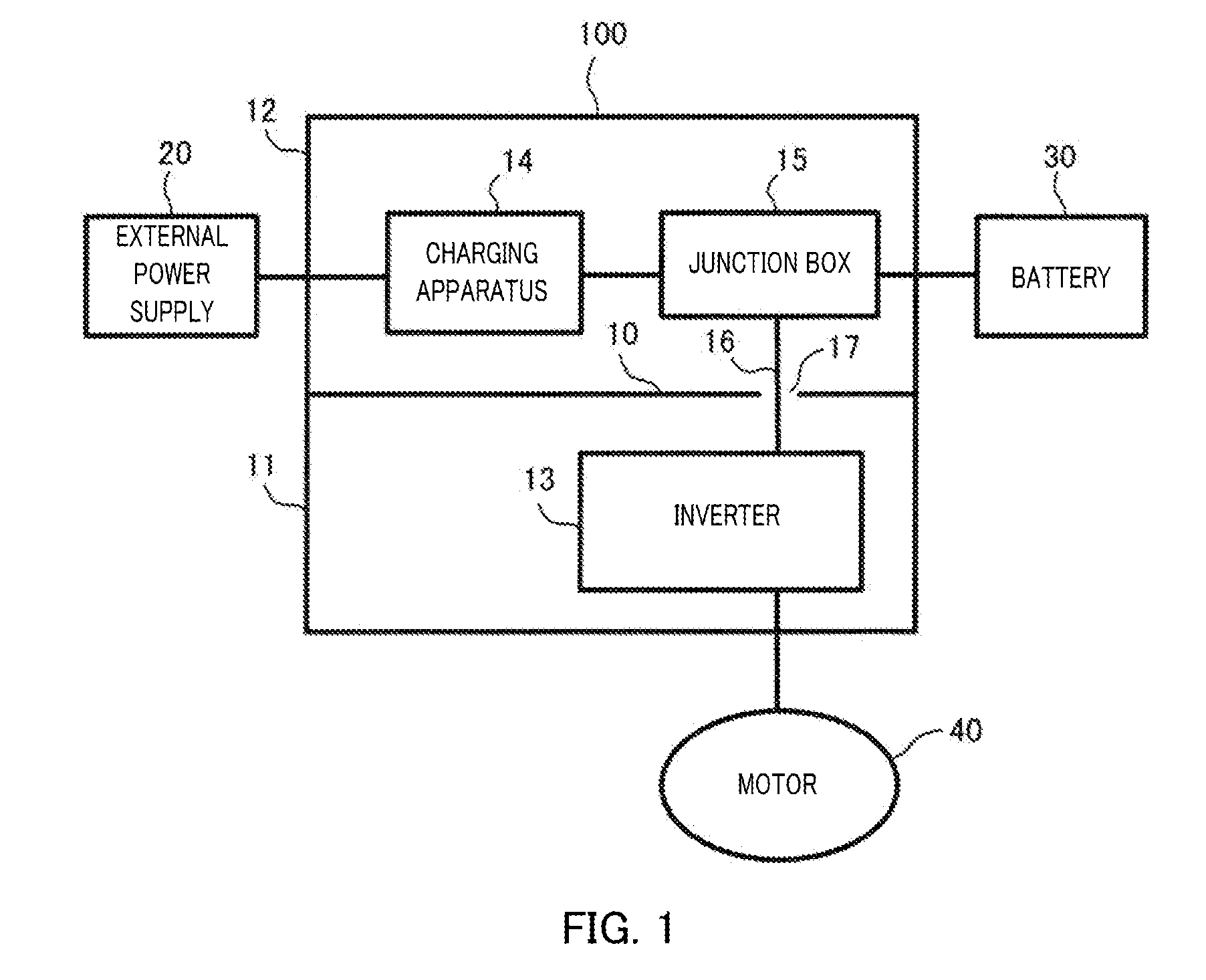
[0023]FIG. 1 is a block diagram illustrating a configuration example of the power conversion apparatus according to Embodiment 1.

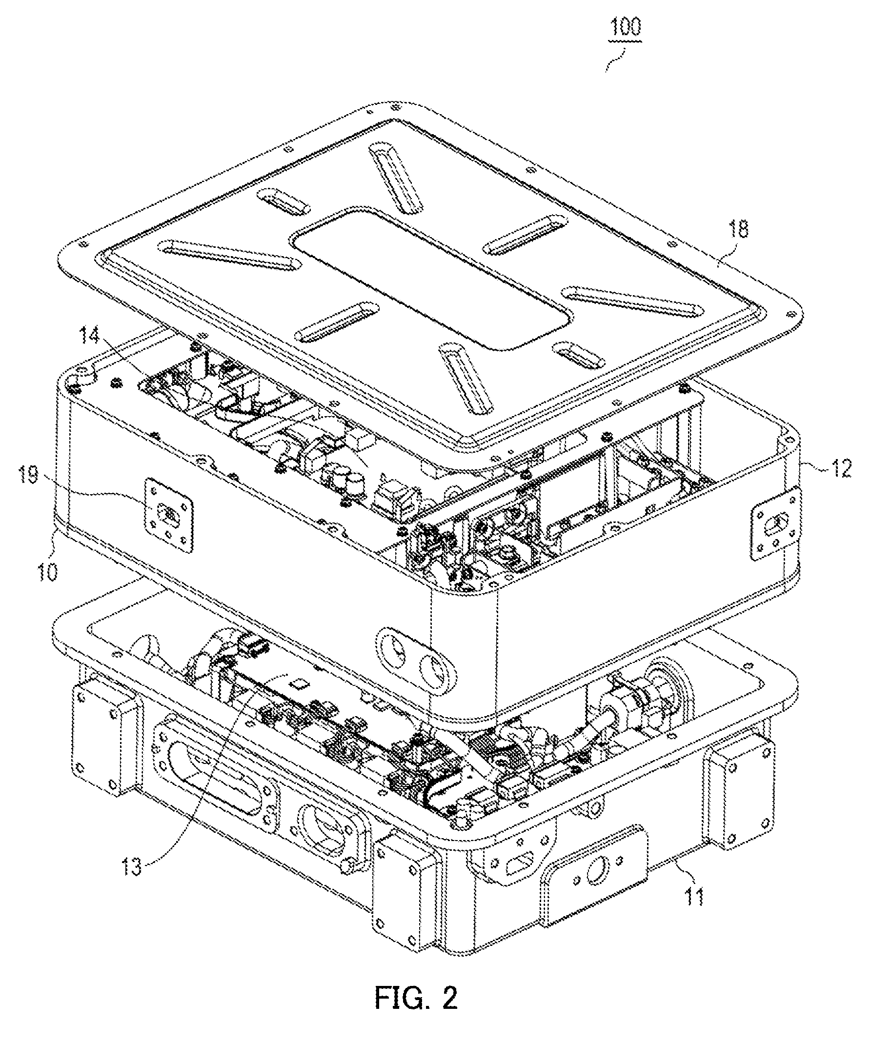
[0024]In FIG. 1, power conversion apparatus 100 is an apparatus to be installed in a vehicle such as an EV and includes: casings 11 and 12; inverter 13, which serves as a power conversion circuit; charging apparatus 14; and junction box 15. In power conversion apparatus 100, a single casing is formed by combination of casing 11 (an example of a first casing) and casing 12 (an example of a second casing) and is divided into casings 11 and 12 by partition member 10. Partition member 10 is a member serving as the bottom of casing 12 (hereinafter, may be referred to as “bottom member”).

[0025]Casings 11 and 12 are molded using an aluminum cast, for example, and are heat-resistant and rigid....

embodiment 2

Description of Embodiment 2

[0069]The basic configuration of power conversion apparatus 100 according to Embodiment 2 is similar to the configuration illustrated in FIG. 1, so that the description will not be repeated. Hereinafter, a description will be given of differences from Embodiment 1.

[0070][Configuration of Work Window]

[0071]In power conversion apparatus 100 according to Embodiment 2, casing 11 includes two work windows 111 and 112 for directly connecting three-phase output cables 42 to inverter 13 as illustrated in FIG. 6.

[0072]FIG. 7 is an exploded perspective view illustrating a structure of the work windows and lids of the power conversion apparatus according to Embodiment 2. FIG. 8 is a perspective view illustrating how the lids are fixed to the work windows. FIG. 9 is a front view illustrating the work windows. FIG. 10 is a front view illustrating how a first lid is fixed to a work window. FIG. 11 is a front view illustrating first and second lids are fixed to the work ...


PUM


Abstract

A power conversion apparatus capable of cheaply securing safety and achieving watertightness. The power conversion apparatus (100) has: a charging device (14) for charging from an external power source (20) to a cell (30); an inverter (13) for converting the current of the cell (30) from direct current to alternating current and supplying the current to a motor (40); and a junction box (15) for relaying an electrical connection. The inverter (13), the charging device (14), and the junction box (15) are contained in a single housing. Also, the charging device (14) and the junction box (15) are electrically connected, and the junction box (15) and the inverter (13) are electrically connected. Also, the junction box (15) and the inverter (13) are connected by a bus bar (16).

Description

TECHNICAL FIELD[0001]The present invention relates to a power conversion apparatus and a junction box to be installed in a vehicle.BACKGROUND ART[0002]In recent years, electric vehicles (EVs) or plug-in hybrid electric vehicles (PHEVs) have become popular. These vehicles each include: a battery; a charging apparatus configured to charge the battery using an external power supply (commercial power supply); an inverter configured to convert a direct current from the battery to an alternating-current; and a motor configured to drive a wheel of the vehicle using the alternating-current from the inverter (e.g., see Patent Literature (hereinafter, referred to as “PTL”) 1. These devices are electrically connected to each other.CITATION LISTPatent LiteraturePTL 1Japanese Patent Application Laid-Open No. 2012-240477SUMMARY OF INVENTIONTechnical Problem[0003]The technique disclosed in PTL 1 adopts a harness as a means for electrical connection, thus connecting devices respectively housed in d...

Claims


Application Information

Patent Timeline
IPC IPC(8): B60L11/18H02M7/44
CPCB60L11/1803H02M7/44B60L11/1809H02G3/088Y02T90/14Y02T10/7072B60L53/14B60L53/22B60L53/00B60L50/66B60L50/51Y02T10/70H05K7/14324H05K7/1432Y02T90/12
Inventor HOSAKA, RYOTAKAKUTANI, KAZUSHIGETAGUCHI, KENJIKAMIYA, TAKASHIYAMAMOTO, NOBUO
Owner PANASONIC INTELLECTUAL PROPERTY MANAGEMENT CO LTD
Why Eureka
Try Eureka